
L-Edit New User Guide
Curt McKenna Fall 2022
Introduction …………………………………………2
Installation ……………………………………………2
L-Edit – Getting Started ………………………..2
New Design
Creating Cells
Basic Shapes …………………………………………7
Drawing Circles
Drawing Rectangles
Drawing Lines
Advanced Commands …………………………..10
Object Snap
Free Movement
Duplicate
Move Command
Rotate Command
Adding Text
Finalization …………………………………………..15

Introduction
This tutorial is meant to assist in first time users getting a background in Layout design. This
tutorial should leave the user with enough knowledge to create a simple photomask design file to be
created using the UofL MNTC mask making service. When the user becomes familiar enough with L-edit
to need resources beyond this tutorial, it is recommended that they refer to the official L-Edit User’s
Guide which can be found in the help menu of the L-Edit program.
Installation
This section will cover how to download and install L-Edit using the services offered by University of
Louisville. These resources are only made available to University of Louisville Students and
Employees
1. Go to the Speed IT Software Share
(it may be mapped to a drive letter, if not enter \\spd-vogt-fs01.ad.louisville.edu\Software in the
address field of Windows File Explorer)
2. If prompted, supply your ULink credentials in the format: ad\username
3. Open the Tanner folder, copy TannerTools_v2019.2-Win64.exe to your desktop and run the
executable
4. Click Install Products, Next, Next, Agree, Install
5. Select yes/no whether you desire desktop shortcuts
6. Click the "Licensing" button
7. Select "Point to a License Server"
8. Ask the MNTC staff for the license location and you can put that file path in the “Port number
and host name” Field
9. Click Next
10. Click No when asked for more licenses to setup
11. Click Exit
Getting Started
New Design
The MNTC website provides a starter file that can help you get started with your design. You can
access it here: ADD WEB ADDRESS. This file includes some features that will probably be helpful to new
users including premade layers, example alignment marks, and individual die separated by dicing
streets. Feel free to use this example file to start your design and if you do so feel free to jump ahead to

“Creating Cells”. If you are interested in starting your design from scratch, then create a new project and
go through the first section of this guide.
The first setting that we are going to modify is going to be the “Design Technology”. The design
technology is where we are establishing the feature size of our layout. This can be accessed by selected
Setup -> Design from the drop-down menu. Once this is selected you should be rewarded with a popup
that looks like this:
This window allows us to select exactly how the drawing is going to be scaled. This is important
in order to prevent your 10 microns feature from ending up a 10 millimeter feature. For all files being
used at the MNTC, the window above shows the optimal settings. The “technology units” should be set
to microns and one internal unit should be equal to a thousandth of a micron. This internal unit shows
the smallest amount of resolution in which the software can operate.
The next setting to examine is going to be the design layers. This step begins with establishing
how many masks are going to be needed. For example, if we wanted to make a simple BJT we would
need three separate regions: An n+, a p, and an n++ region. Since each region will require its own
photomask we will need to establish three different layers for our BJT. However, also keep in mind that
we should have an additional mask used for creating contacts to these regions. Because of this we will
need four masks for this example.

The layout palate can be seen on the left side of the screen in the window shown above. In this
window, the uppermost field shows the currently selected layer (in this case “Deep N Well”). The drop
down box allows you to select which of all of the available layers are shown. In addition to the name of
the layer you will notice a square to the left showing an example of the color polygons drawn in this
layer will appear in your design. You can also click on the radio box under the “shades” icon for each
layer to hide their appearance in your design (just make sure to re-enable them before finalizing). You
will also notice a number which will be used to represent that layer when we finalize the design. You
will notice the guide layer does not have a number, because it is strictly used for temporary drawings
and guidemarks that we do not want printed in the final design. For our example we are using four
different layers: “N well”, “P well”, “Deep N well”, and “Metal1” plus one additional layer called
“Guide” that won’t be used to create a mask but we will use to help us visualize our design.
Before finishing with the layers, however, it is important to be sure that each of the layers is
properly defined. Most KORE masks should be made in GDSII format, so it is important that we adjust
the settings to our layers so that they can be properly exported into that format. This is done by double
clicking on each of the layers that are being used to bring up a window that looks like this:

When exporting to a GDSII format, the names of the layers are lost. Instead each layer is defined
by the “GDSII number” seen in this window. Therefore it is important to ensure that each layer used has
a uniquely defined GDSII number and all mask instructions reference this number. The numerical value
itself is not important to the mask, so it can be arbitrarily assigned so that it is uniquely defined from all
other layers drawn in the file. Choose any unique number from 1 to 100 for each layer. You should also
feel free to change to the rendering tab to change the way the layer appears as you draw it. It is
necessary that each layer you are using has a distinct appearance to make design easier.
The last setting to check before designing your photomask is to ensure you have the correct
toolboxes available. These toolboxes are located at the top of the display and allow you to easily draw
complex structures onto your design.
These toolbars can be edited by right-clicking anywhere in the toolbar region. Right-clicking
gives you the ability to define which toolbars are shown along with what is displayed within the toolbar
that you right-clicked on. In the case of the following image the “drawing” toolbar was right-clicked,
giving us the opportunity to define what is being displayed within that toolbar.
One of the drawing tools that many people need for MEMS applications is curve tools. By
default these tools are not displayed, but by selected “All Angle & Curves” from the drop-down box we
can select these tools directly from our toolbar. Try displaying the different toolbars and adjusting their
contents to see what is the right display to make designing easier for you.

The last area before we get into designing is to cover navigation, specifically moving across the
design and zooming. The easiest way to move across the design is to use the arrow keys. Unfortunately
this moves the image by a set percentage of the image, so to make fine adjustments the zoom must also
be used. Zooming can be performed using the plus and minus keys
Cells
Cells are a key component of LEdit design philosophy. A cell is a feature in L-Edit that allows
users to easily save and reuse a drawn architecture over the course of the entire design. This feature can
best be visualized as a rubber stamp with a custom face, allow the user to stamp an image as many
times as they want. However, this stamp can be edited even after it has been used throughout the
design and the changes will propagate immediately. Design in microfabrication is frequently done
iteratively, will minor redesigns and adjustments. Utilizing cells will make future revisions (and changes
while you work) much less time consuming.
In microfab design, you will usually have a different cell for each of your different die designs (if
you have multiple). If all your different designs share a same general architecture it may be a good idea
to construct one cell that holds a framework and utilize that cell in all your individual design cells where
you fill in the finer details. Cells can be used within each other any number of times, so feel free to
utilize many cells to make your designing easier.
To begin using cells, go to Cell -> New View to receive a window where you can specify the name
of the new Cell. Make sure to give it a name that will inform you of what it contains, you many
eventually have many cells so the ability to find the cell you want it key to its convenience. Generally,

the first cell you should make should be called “Final Design” where you will place all the other cells to
create your finalized design. There is a good chance the only polygon drawn in this cell will be a circle in
a temporary layer so that you can align all your features within your expected Silicon wafer. If you want,
you can go to Cell -> Fabricate to set a label on the final design. As you can see in the following example
my final design is highlighted with an “f” to show that it is the design that will be fabricated. You can
access all the cells in your design by changing the window to the left to “libraries” as shown here.
There is one last important thing to remember when using cells, and that is that you must
flatten your design before exporting it. Flattening is a process where the software permanently draws
the contents of a cell onto the design. You can do this by selecting Cell -> Flatten. After flattening a
design it will change as though everything has been drawn in that single cell instead of being comprised
of other cells. Flattening is important because the exporting software will not properly read the design if
it is not done. Be cautious with Flattening, however, because you will no longer be able to make changes
in other cells and have the effect carry over onto your main design. It is for this reason that we
recommend that the user does not flatten their cell until they are ready to export. It is also
recommended to keep a saved file from before flattening in case changes need to be made in the
future.
Basic Design
We are now finally prepared to begin designing. There are many different techniques for how to
begin a photomask layout, but perhaps one of the most common is to draw a wafer so that you can
better visualize where other features will be located.
Drawing Circles
To begin, select the “Wafer” layer in the layer palette on the left side. This layer will only be
used to assist in drawing. We do not want it to appear in the final masks, but it can help us at this stage

as we compare the relative size and layout and how things will position on the wafer in the final
product. The crosshair on the display marks the origin, so we can draw a circle originating from that
point to represent our wafer. To begin drawing this circle we select the circle icon in the drawing toolbar
that we modified earlier.
Now click and hold the mouse button near the origin and slowly draw it away from the origin.
Where you initially click will determine the center point of the circle and wherever you let go of the
mouse will determine the radius of the circle. The numerical display in the upper left corner will show
the coordinates (in microns) of your mouse as you move around - use this to get your circle near the
appropriate size, although don’t worry about being to accurate yet. This display shows the distance from
your previous mouse click, first the x distance, then the y distance, then the absolute distance.
Unfortunately, it can be very difficult to get designs like this to be the exact right size with simply
the mouse, so just give it a quick best effort attempt. After this and for most of our drawings in L-Edit
we will use the edit command to exactly size anything we have drawn. So, after you have drawn a circle,
hit Ctrl+E. This should bring up an edit screen similar to this:
Here we can input the exact size of our desired circle. In our case we want it to start and the
origin and have a radius of 50,000 microns, the rough dimensions of a 4” wafer. Therefore we simply
input these values into the editor as shown above and it will automatically resize our circle. Also, if you
forgot to select the wafer layer for this circle we can do so here at the top of the window. This will

remain true for all drawn objects within the editor. You can also select any drawn feature by switching
to the mouse arrow in the drawing toolbar.
Now that we have our wafer, we can begin to draw our smaller features. While your inclination
might be to start hitting the plus sign to zoom in and start drawing, usually it is best to draw individual
devices in a separate cell, especially if you are planning for this design to repeat over the wafer.
Creating Rectangles
To draw square or rectangles, select the rectangle icon from the draw toolbox.
Square features are drawn much the same way as circles - by clicking at one corner of the
desired rectangle and dragging the mouse to where you want the opposite corner. It is also advisable to
edit the figure after it has been drawn to ensure that it is placed exactly where it needs to be and to be
sure that it connects to any necessary structure. There is no negative effect to having two objects of the
same layer overlap, the software will simply treat them as a single entity. The edit screen for rectangles
can be brought up with Ctrl+E and should look like this:

This mode allows you to edit each of the corners of the rectangle individually to ensure the
correct alignment. Many other figures are drawn similar to the rectangle, so explore others to see if they
can make drawing your design easier.
Creating Lines
Drawing lines is slightly different than drawing the circles and rectangles that we have already
done. The key difference is that we must set a line width before we begin drawing. This can be done by
selecting where is says default and changing it to other:
This will bring up a window that will allow you to select the width, in microns, for any future
lines you draw. Now that we have set the desired line width, we can draw some of your lines. There are
three types of lines to choose from: orthogonal, 45 degrees, and any angle lines. Use the simplest
method for your application. All lines are drawn by selecting starting and ending points. To draw a single
line, left-click at the starting point and then right click at the ending point. To draw a continuous line
that turns, left-click at the starting point and left-click at each corner until you reach the ending point
where you can right-click. This is a little counter-intuitive and takes some getting used to. The editing
tool can be used here also to modify the coordinates of each point in the line. Another important thing
to mention is that the line that the computer generates expands in all directions from the line that you
draw. An example of this is shown here:
The small black line shows the actual starting and ending points the user selected. However, due
to the fact that the line width was set at 1 micron, the computer adds .5 microns to all sides of your
drawn line. Keep this in mind when you are trying to line up lines with other objects.
Advanced Design
One of the first things you will realize when designing using basic principles is that it is very time
consuming to make sure everything lines up properly. This section will cover some of the more
advanced tools that may not be needed for every project, but will prove to be a real asset when it comes
to speeding up the design process when they are applicable.

Object Snap
Object snap is one of the tools that will be useful to most any project you are designing. Object
snap allows you to anchor parts of a polygon with already drawn features (either on your current
drawing layer or another one). Object snap can be seen at the top of your screen and should look like
this:
First you will want to make sure that the highlighted button (magnet icon) is activated. This is
the command to turn on object snap. Now, whenever your mouse hovers over the relevant feature on a
drawn layer you will see a red graphic pop up to show any drawing you currently make will be anchored
to that point. As far as which features the software will try to anchor, that depends on which of the
icons to the left are activated.
This icon will allow you to anchor to any vertexes on any existing polygons
This icon will allow you to anchor to the midpoints of any line or side of a polygon
This will allow you to anchor anywhere along an existing line or side of a polygon
This will allow you to anchor to the intersection of any two lines or polygons
This will allow you to anchor to the centerpoint of any circle, wedge, or torus you have
drawn.
This will allow you to anchor to the quandrants of a circlular figure (0°, 90°, 180°, 270°)
This will allow you to anchor to drawn text fields and ports, which are not covered in this
tutorial.
Free Movement
Sometimes it may be beneficial to move an existing object without worrying about exactly
where it is positioned. To do this free movement we can select the object we want to move and as long
as you hold the ALT key you will be able to move it around freely based on your mouse movement. We
can also move multiple objects at the same time by selecting them by clicking and dragging or holding
the SHIFT key while you click on different objects. If two objects are overlapping, you can click on the
same space twice and it will rotate between the different objects.
Duplicate

As you may have noticed if you have been following all of the steps so far, it can take a long time
to create an entire wafer’s worth of architecture using only the basic commands. This section will help in
finding ways to quickly replicate what you have already drawn to fill up your design much faster. The
first command that we are going to look at is going to be the duplicate command.
Before we learn the duplicate command, we should learn how to select objects that have
already been drawn. This can be done by selecting the mouse pointer in the drawing toolbar shown
here:
Using the pointer we can select individual objects that we have already drawn. You can select
multiple objects by holding shift while clicking on them with the mouse pointer. Once we have selected
the appropriate object we are prepared to use the duplicate command. The duplicate command is in the
editing toolbar shown below and only becomes visible when at least one object is selected:
This command will take whatever object is currently highlighted and create an exact duplicate of
it in the exact same coordinates. This new object can then be moved, flipped, or rotated using various
commands in the editing toolbar. One option is that you can immediately hit CTR+E to edit the
coordinates. Another option is the move command, which is especially useful because it can be used to
create arrays.
Move Command
The move command is in the editing toolbar and is shown here:
The move command allows the user to adjust the location of the currently selected object(s) by
an arbitrary amount. The object(s) will retain all of their previous dimensions. Using this command
immediately after the duplicate command allows us to move the newly created object while keeping the
original. The window that pops up when Move is selected should look like this:
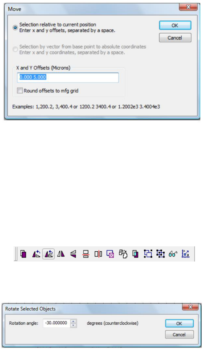
With this window we can input the change in x and the change in y we desire, making sure to
separate them with a space. Hit “OK” to immediately move the object. You will notice the moved object
will remain highlighted once the process is complete. This is because L-Edit has added a nice feature in
that if you press duplicate again it will automatically apply the move command to the newly created
object relative to the one you just created. Therefore the result of rapidly hitting the duplicate
command after using the move command will be to quickly create an array of objects.
Rotate
The other editing command that is worth mentioning is the rotate command. This command is
very similar to the move command except that it moves the object rotationally instead of translationally.
This command can be found in the editing toolbar as shown here:
The rotation command can be applied to any selected object and will move that object by any
amount specified by the user. When the command is called a window like this will come up: Simply input
the degree change you desire into the rotation angle field.
Keep in mind that this rotates your object by its geometric center in a counterclockwise motion.
Using this command can be much simpler than trying to create these complex structures using the basic
commands. Please explore the other tools in the editing toolbar to help in making other complex
designs.

Adding Text
One of the final touches you may want to put on your design is add text. It can be useful to label
areas for certain purposes, or to label feature sizes so that they are written on the mask and can be
easily found later. To add text you will want to go to Draw -> Layout Generators -> Layout Text
Generator:
This will bring up a window where can modify how the text will be generated. The first field to
look at here is the “Layout Text String” where you will want to input the text you wish to generate. Next
move down to “Layer Name” which will determine which layer this text will be created in. “Text Size”
will determine how large this text will be, but the actual size does not seem to follow the number here
exactly so it may be necessary to try a few times before you get the size you want. The last option you
may or may not utilize is “Create as Instance”. If this is checked, it will create the text as a separate cell

in your design which may be beneficial to you if you plan to use this text regularly over the rest of your
design. If not checked it will just generate a series of polygons on your current cell.
Finalization
This last section will cover what needs to be done to export the design so that it can be
processed by The UofL Micro Nano Technology Center. The exporting process itself is very simple, just
select File -> Export Mask Data -> GDSII. You will be greeted with a pop-up window where you should
select these settings (make sure you select your main design cell where it asks for your export cell):
Before you use this export command, it is important that you perform one last check to ensure that your
file is completely ready for exporting. The two important things to remember are making sure that you
have GDS labels for all your used layers and flattening your design cell. Labeling your layers was
discussed in the “Getting Started” section of this guide and flattening cells was discussed at the end of
the “Cells” section. Please review these sections before exporting if you have not already addressed
these issues.
