
CFC / ICAC / 11 Project Technical Report on Research Activities Page 177
C.5. Effects of relative humidity on the spinning process and yarn quality
C.5.1. Objective
It is possible, through measurement of the stickiness of raw cotton, to predict the disruption
that may occur during spinning. Now, this experiment is designed to answer the question:
what is the effect of relative humidity on the spinning process and the quality of the yarn ?
C.5.2. Materials and methods
Seven cottons were selected from the 24 cottons spun at ITF during the industrial spinning
study to cover a range of stickiness. These cottons were obtained from the Laroche mix. One
spinning test was performed for each cotton with two types of spinning – open-end or rotor
spinning (OE) and ring spinning (RS) in three relative humidity conditions (40, 45, 55%).
For industrial carded varieties of cotton, the procedure is as follows: first opening and
blending of cotton, then carding, condensation of the web in a sliver, drawing steps, flyer and
spinning. As far as the micro-spinning is concerned, the previous procedure was adapted in
line with the quantity of the cotton fibers to be spun (Frydrych and Dréan, 2000).
The micro-spinning stages for an amount of cotton ranging from 50 to 500g are shown in
Figure C-1.
Cirad uses Platt micro-spinning equipment which consists of a mini-card, a drawing frame
and an eight-spindles spinning frame with double drawing, as well as six Suessen open-end
rotors.
C.5.2.1. General micro-spinning steps
The full set of spinning tests were to be conducted in three steps (Figure C-1).
C.5.2.1.1. First step: opening and carding
Fiber preparation consisted of blending, cleaning, disentangling fibers. It could be split into
the two following stages:
- cotton opening and blending on the Cirad cotton opener for samples of 50 g and over;
samples of 250 g to 500 g were split into 5 parts of 50 or 100g.
- carding operation provided the cleaning, disentangling and paralleling of fibers while
eliminating a part of the neps and short fibers. Depending on the starting weight of the
sample, i.e. 50 or 100 g, the outgoing web of a weight of 5g/m² was taken by the cylinder,
with respective lengths 0.77 m or 1.57 m. In our case, the 5 sub-samples were carded into
5 fleeces.
C.5.2.1.2. Second step: drawing
The drawing consisted in passing the fibrous flow (fleece or sliver) between four pairs of
pressing cylinders, driven at different tangential speeds. In all cases, it was necessary to
perform three drawing operations. The first passage changed the card outgoing fleece into a
sliver. The two other operations correspond to those performed in an industrial plant. Two
methods:
- sliver from the sample of 50 g is collected on a drum;
- sliver from the sample of 250 g and over is collected in cans.

CFC / ICAC / 11 Project Technical Report on Research Activities Page 178
In our case, we ran our 5 fleeces of 100 g on the first pass of the drawing frame to produce 5
slivers. These 5 slivers altogether (for a doubling) fed the second passage on the drawing
frame to produce 10 slivers. For the third passage, the 10 slivers altogether (for a doubling)
fed the drawing frame to produce 4 cans (one can per spinning position for both OE and RS
spinning).
C.5.2.1.3. Third step: ring spinning and rotor spinning
Spinning consists of winding the yarn on a support. The two main types were being used: ring
spinning (RS) and rotor spinning (OE).
The micro-spinning methodology for the relative humidity study is described in
Figure C-2.
For this study we used methodology based on 500 g of cotton per test, with the two types of
spinning (OE and RS). This methodology was duplicated for each of the three ambient
conditions: 40%RH and 27 °C, 45
%
RH and 22 °C; 55
%
RH and 27 °C.
During industrial spinning at ITF, eight kilograms of fibers per cotton were taken from the
Laroche opening machine for the seven selected cottons. One kilogram from each was
sampled for each relative humidity condition, 40%, 45%, 55% per type of spinning.
For each humidity condition and for each cotton, 10 samples of 100 g were worked out per
spinning. Different yarn counts were performed depending on the spinning process: 20 tex for
the ring spinning process, and 27 tex for the open-end process.
The randomization designated work at 45
%
humidity first, then at 55
%
, and finally at 40
%
RH.
The order in which the seven cottons were spun in each humidity experiment was randomly
organized.
The organization of this experiment is illustrated in
Figure C-2 and discussed below.
C.5.2.1.4. Opener
Twenty samples of each cotton (100 g x 10 for RS, 100 g x 10 for OE) were prepared one
after the other. No notes were taken since this was simply an opening / blending operation of
the raw material.
C.5.2.1.5. Mini-card
Stickiness level was evaluated during the carding on the small cylinder (perimeter = 0.77m).
The evaluation was made fleece after fleece, and also taking care to the time. Four grades of
stickiness were defined:
- grade 1; non sticky, no deposit on the 2 cylinders (upper and lower);
- grade 2; slight stickiness; some deposits, some rising, possible rolling up;
- grade 3; medium stickiness; rising and many deposits, rolling up;
- grade 4; high stickiness; high rising, many deposits, high rolling up, web break.
The evaluation time was up to rolling-up while recording the time required to get them. Then,
in case of sticky cottons, after 3 rolling up, the cotton was considered as highly sticky, and the
upper cylinder of the card was removed to continue the carding process of the remaining
cotton sample.

CFC / ICAC / 11 Project Technical Report on Research Activities Page 179
The outcome products at the card level are 20 fleeces (100 g each, Slide C-1). In order to
produce two replicates of RS and OE yarns, this set of 20 fleeces is divided into 2 groups of
10 fleeces, each group being processed by a doubling of 5 fleeces. Thus 4 groups of fleeces
were processed on the drawing frame: 5 fleeces for RS, repetition 1; 5 fleeces for RS,
repetition 2; 5 fleeces for OE, repetition 1, 5 fleeces for OE, repetition 2 respectively.
C.5.2.1.6. Drawing
For each spinning repetition, 5 fleeces were transformed to form sliver (Slide C-2 to Slide
C-4). The drawing roller was cleaned between each 500 g or following accumulation of
stickiness which led to breakage of the sliver. All the incidents, interventions concerning the
rolling-up were noted. The slivers from each repetition were collected in 4 cans for the ring-
spinning and 2 cans for the open-end spinning.
C.5.2.1.7. Ring spinning
The four slivers of stickiness for each repetition were spun on 4 independent spindles (Slide
C-5).
Each spindle produced 8 cops (1 cop at each doffing).
Observations made during spinning, and mainly at the back drawing of the spinning
concerned:
- spinning disruptions or breakages (induced or not by stickiness);
- presence or absence of sticky points deposited on the back draught roller (in some case,
we also noted deposits on the front roller) causing the fiber to wrap around the roller;
- manual interventions or cleanings to prevent spinning from being interrupted.
C.5.2.1.8. Open-end
Two slivers were used per repetition. Each sliver fed one rotor and gave 1 bobbin per
repetition. Observations made during spinning concern:
- number of spinning disruptions or yarn breakages (induced or not by stickiness)
- number of rotor cleanings.
C.5.2.2. Yarn quality characterization
C.5.2.2.1. UT3 evenness tester
The following evenness tester machine settings were used:
- RS: speed 100 m/min, thin (-50%), thick (+50%), neps (200%), slot 1 (20 tex)
- OE: speed 100 m/min, thin (-50%), thick (+50%), neps (280%), slot 2 (>21 tex)
The tests were conducted as follows:
- Yarn tests in ring spinning
Every cop produced was UT3 tested (i.e. 64 cops * 250 m/cops = 16000 m tested).
- Yarn in open-end
2 repetitions x 2 bobbins x 1 km x 4 measurements, i.e 16000 m.
- Detailed analysis of RS yarn: a detailed neps analysis was performed using a method

CFC / ICAC / 11 Project Technical Report on Research Activities Page 180
developed at Cirad to identify the different types of neps observed. During this measurement,
the evenness tester stops the flow of the yarn at the appropriate position so that every nep is
examined in detail through a magnifying lens under intense light and classified as seed coat
fragment, fiber neps, (entangled and sticky neps), fragments such as leaves or sticky neps.
Percentages obtained for each type of imperfection were adjusted to total neps on 1000 m to
obtain the number of neps per type of imperfection on 1000 m. This detailed analysis was
performed on 1/8th of the cops produced on 1000 m of yarn (first doffing of 4 cops per
repetition) for a total of 2000 m.
- Detailed analysis of OE yarn: the same method as for ring spun yarns was employed to
characterize the neps on OE yarn on 4 bobbins with 2 measurements (1000 m each) for a total
of 8000 m.
C.5.2.2.2. Tenacity using Tensorapid 3
Yarn strength took account of the yarn count as determined by UT3 measurement.
- Ring spinning
Only 3/8th of the 64 cops were tested on Tensorapid because testing time was long
(20 seconds per break, 40 breaks / cop) for a total of 960 breaks. The cops chosen
corresponded to the first, fourth and eighth produced at each single spinning position. Thus,
12 cops were tested per repetition.
- Open-end
Two bobbins * 2 repetitions x 40 breaks x 4 measurements = 640 breaks.
C.5.3. Results and discussion
C.5.3.1. Effect on the spinning process
C.5.3.1.1. At the card level
The figures below only show a fitted line if a significant relation was detected between the
measured criteria and the stickiness level of the given cottons.
Figure C-3 shows that stickiness had a significant effect on the rolling-up at the card level
when RH was 45%, while no trend was noted at 55%RH since it appeared to bring immediate
troubles for any cotton stickiness level. None of the cottons caused disruption at 40
%
RH. A
saturation effect was noted in the number of rolling-up at 55%RH because the operating
procedure employed did not record any rolling-ups after the third occurence. Some examples
of the effect of stickiness at the card level are given in Slide C-6 to Slide C-9.
It should be noted that these results take account of the accumulation of stickiness
phenomena occuring for a complete set of 10 fleeces except when more than 3 rollings-up
occured.
As far as time till onset of rolling-up is concerned, the highest relative humidity levels (45
and 55% RH) were seen to have a significant effect, as illustrated in figure C-67. Any rolling-
up at 40% occurred after a very long time (as shown in figure C-66 for the most sticky
cotton).
C.5.3.1.2. At the drawing frame level
A significant relation was noted between the number of rollings-up and the stickiness level at
55%RH (Figure C-5). However, the number of interventions (where production did not need

CFC / ICAC / 11 Project Technical Report on Research Activities Page 181
to be halted, Figure C-6) and cleaning (the machine is stopped for this operation, Figure C-7)
on the drawing frame increased with stickiness as soon as the relative humidity increased.
Some stickiness-induced problems are shown in Slide C-10 and Slide C-11.
C.5.3.1.3. At the OE spinning level
A trend was noted between breakages and stickiness for the highest RH (Figure C-8), while
no significant relation was found concerning the cleaning of the machinery (Figure C-9).
It should be noted that cleaning operations were only performed after a breakage, and only if
a sticky deposit was observed in the rotor (Slide C-12 and Slide C-13).
C.5.3.1.4. At the Ring Spinning frame level
Figure C-10 shows the number of cleanings required to render the machine productive. These
cleanings were performed when yarn production was stopped (the yarn was broken) unless
this cleaning was required to maintain yarn production (for instance, when too many breaks
were observed in a short time due to stickiness accumulation).
At 40
%
RH, almost no cleaning was required to maintain production, whatever the stickiness
level of the raw cotton. At 45 and 55% RH, cleaning was required to maintain yarn
production.
The overall increase in the number of interventions, as a function of RH and stickiness levels
during these experiments on all machines we used, probably had an effect on the quality of
the yarn. Thus, the cleaning and intervention operations removed some potential irregularities
from the yarn. In other words, our interventions were performed to maintain yarn production,
but they also indirectly improved the final quality of the yarn. Thus, the yarn quality results in
this experiment were not only dependent on stickiness and RH% conditions but also on the
number of cleaning/interventions. We will have to take this into consideration when looking
at yarn quality results below.
C.5.3.2. Effect on yarn quality
Depending on the type of spinning (RS or OE), different categories of neps were counted on
the yarn by the evenness tester as defined in standards: neps 200
%
for RS yarns, and neps
280
%
for OE yarns.
C.5.3.2.1. Quality of Ring Spun yarns:
An analysis of variance of the results of this study was performed in a split-plot factorial
(1/2*3) design for the main yarn quality characteristics. The results are presented in Table
C-1. Data for the counts were assumed to follow a Poisson distribution because their
distribution should be even within the yarn because of the mixing process conducted while
spinning. Thus, to normalize their variance, these counts were transformed through a square
root calculation. However for clearer understanding of the results, the charts use raw and real
scale data.
Table C-1: Analysis of variance of the data collected in the RH experiment on RS yarns.
RH SUDAN YARN ANALYSIS, 3 HUMIDITIES, 7 COTTONS, Ring Spinning, 2 SETS
File: RH UT3 Title: RH SUDAN UT3
NUMBER of OBSERVATIONS: 84
DISPOSITIF DE L'ESSAI: SPLIT-PLOT 1/2

CFC / ICAC / 11 Project Technical Report on Research Activities Page 182
FACTEUR 1: 3 HUMIDITES 40% (40%), 45% (45%), 55% (55%)
FACTEUR 2: 7 COTONS 1 (AS02), 2 (AS09), 3 (AC1), 4 (AS04), 5 (AS10), 6 (AS20), 7
(AS05)
FACTEUR 3: 2 BLOCS BLOC 1 (B1 ), BLOC 2 (B2 )
CVM RAC.
THIN
RAC.
THICK
RAC.
NEPS
200%
Hairiness
Yarn
Elong.
Yarn
TEN.
Yarn
CV TEN.
Res.
Suspects
00022000
F Hum. 0,0056 0,0021 0,0056 0,0306 0,1501 0,0010 0,0111 0,0853
ETR 1 0,19 0,69 0,48 1,33 0,19 0,04 0,16 0,37
CV 1 (%) 0,8 2,5 1,3 4,2 3,1 0,8 1,3 2,8
F Cot. 0,0000 0,0000 0,0000 0,0000 0,0000 0,0000 0,0000 0,0000
Int. H×C 0,0000 0,0012 0,0000 0,0000 0,0000 0,1042 0,1272 0,0273
ETR 2 0,23 1,19 0,86 1,22 0,06 0,10 0,29 0,78
CV 2 (%) 1,0 4,4 2,3 3,9 0,9 2,0 2,3 5,9
Gen.
Mean
23,05 26,95 37,25 31,28 6,11 5,21 12,53 13,21
40
%
45
%
55
%
23,75a
22,70b
22,72b
30,74 a
25,93 b
24,18 c
38,99 a
36,33 b
36,43 b
32,43 a
29,04 b
32,37 a
6,23
6,13
5,98
5,57 a
5,11 b
4,97 c
12,22 b
12,44 b
12,94 a
13,55
12,89
13,19
1 (AS02)
2 (AS09)
3 (AC1)
4 (AS04)
5 (AS10)
6 (AS20)
7 (AS05)
23,76b
24,13a
20,28d
23,64b
24,01ab
21,72c
23,84ab
29,32 bc
32,62 a
15,68 e
29,96 b
30,44 b
22,50 d
28,14 c
40,49 a
40,02 a
29,40 d
38,48 b
39,94 a
32,17 c
40,25 a
37,97 a
29,35 c
27,52 d
29,21 c
32,87 b
24,98 e
37,08 a
6,13 d
6,42 b
5,21 f
6,57 a
6,40 b
5,81 e
6,26 c
5,34 b
4,94 d
5,59 a
4,79 e
5,02 d
5,61 a
5,20 c
12,43 c
11,42 e
14,16 a
11,86 d
12,05 d
13,21 b
12,59 c
12,82 cd
14,14 ab
10,94 e
14,89 a
13,59 bc
12,34 d
13,75 abc
As stated in many publications, yarn quality is dependent upon fiber quality. In this study,
stickiness had difference effects on yarn quality depending on the relative humidity in the
spinning room. However, since most of the cottons used in the study were of similar quality,
most of the effects observed were considered to be due to stickiness. Nevertheless, care
should be taken when considering the results and a check should be performed to verify
whether the effect is due to stickiness or fiber quality parameters.
Relative humidity had a critical effect on yarn quality characteristics, and in particular by a
change in the evenness counting for irregularities.
The figures in Table C-29 illustrate the relations described. A fitted line is only displayed in
the figures below if a significant relation exists between the measured criteria and the
stickiness level of the given cottons. In some figures, no significant relationship was detected

CFC / ICAC / 11 Project Technical Report on Research Activities Page 183
for any of the cottons, but one may appear to be highly significant for the cottons considered
to show ‘low to medium’ stickiness. In these cases, the fitted line were drawn for these
cottons. We give the analysis of variance results (drawn from Table C-1) in the upper right
hand corner of the picture.
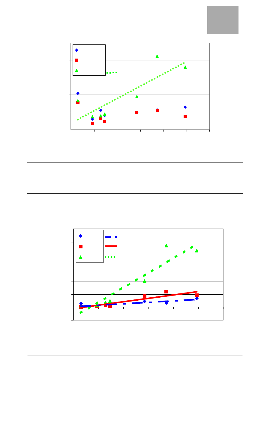
Figure C-11 shows a significant increase in Thin places in the RS yarn spun using cottons
with a low stickiness level. For all humidity levels, the number of thin places showed a
similar trend toward saturation when stickiness exceeded 20 sticky points. However, it was
noted that more thin places occurred at lower humidities compared to other conditions.
Figure C-12 shows the relation the number of thick places plotted against RH% and
stickiness. The only significant relationship was noted at 55% RH between the number of
thick places and stickiness.
Figure C-13 shows that RH and stickiness had a significant impact on the number of neps
(200
%
) in the yarn. However, a significant interaction induced a greater sensitivity to
stickiness at higher humidity. It was also observed that the number of neps was higher when
slightly sticky cotton was spun at 40% RH compared to the results when the same cotton was
spun in 45 and 55% RH.
Moreover, a detailed analysis showed that stickiness increased the number of sticky neps
(Stk, Figure C-14, Slide C-14), and also the number of fiber neps at all RH values (F, Figure
C-15) under 45 and 55
%
RH conditions.
A significant relationship was noted solely between yarn strength and stickiness at 40
%
RH,
even though the pattern at other humidities was similar (Figure C-16). This trend can be
explained by the fact that stickiness induces irregularities that creates weak points in the yarn
(as well as seed coat fragments, Krifa, 2001). This can be proven by counting the seed coat
fragments present in the card fleeces (Figure C-17), where both counts (on yarn and on card
fleeces) follow the same trend.
Figure C-18 shows that the cotton which appeared to show little stickines contained many
seed coat fragments that significantly affect yarn strength. Thus, the trend observed in Figure
C-16 for the lower stickiness level cannot be considered as significant.
In most of the figures, a saturation effect was observed in the relations with stickiness. As
stated above, interventions were made during the experiment to allow yarn production (these
interventions were mainly performed for heavily contaminated cottons, Figure C-7 for
instance), but was assumed indirectly to improve yarn quality. This hypothesis cannot be
proven since it is impossible to predict what kind of defect we avoid by cleaning the spinning
frame. However, this assumption can be proven by looking at the relationships between the
main criteria (such as the number of thin and thick places and yarn strength) and stickiness:
when few interventions are required to spin (non sticky cottons), we observe significant
relations between the ‘yarn quality criteria’ and stickiness; as soon as the number of
interventions increases, the relation between ‘yarn quality criteria’ and stickiness becomes
non-significant and a saturation effect occurs.
The trend observed on the left of Figure C-16 does not continue to the higher level of
stickiness since interventions and cleaning were performed to allow yarn production. Thus,
we can assume that the number of irregularities was decreased artificially by the cleaning, and
the number of weak points in the yarn decreased accordingly. However, this assumption
should be checked using the new Tensorapid testing methodology and a new way to analyze
the dataset (empirical quantile / quantile plot method, Krifa, 2000, 2001). This methodology
can be used to analyze the interaction between fiber quality and/or contaminant on yarn

CFC / ICAC / 11 Project Technical Report on Research Activities Page 184
quality parameters.
C.5.3.2.2. Quality of Open End spun yarns:
An analysis of variance based on in the same design as for RS yarns was performed on the
data. The results of this analysis are given in Table C-1. Counting data are assumed to follow
a Poisson distribution because they should be evenly spread within the yarn because of all the
mixing processes conducted while spinning. Thus, to normalize their variance, these counts
transformed through a square root calculation.
Table C-1: Analysis of variance of the data collected in the RH experiment on OE yarns.
RH SUDAN YARN ANALYSIS, 3 HUMIDITIES, 7 COTTONS, Open End , 2 SETS
File: RH UT3 TITLE: RH SOUDAN UT3
NUMBER OF OBSERVATIONS: 84
DISPOSITIF DE L'ESSAI: SPLIT-PLOT 1/2
FACTEUR 1: 3 HUMIDITES 40% (40%), 45% (45%), 55% (55%)
FACTEUR 2: 7 COTONS 1 (AS02), 2 (AS09), 3 (AC1), 4 (AS04), 5 (AS10), 6 (AS20), 7
(AS05)
FACTEUR 3: 2 BLOCS BLOC 1 (B1 ), BLOC 2 (B2 )
CVM RAC.
THIN
RAC.
THICK
RAC.
NEPS.
280%
Hairiness
YARN
ELONG
YARN
TEN.
YARN
CV TEN.
Rés.
Suspects
22222002
F Hum. 0,1196 0,0287 0,0530 0,0037 0,2111 0,0093 0,6067 0,1901
ETR 1 0,75 0,55 0,85 0,41 0,66 0,23
,42
0,59
CV 1 (%) 4,8 11,1 9,0 5,3 12.2 ,3,2 4,2 5,6
F Cot. 0,0823 0,0124 0,0006 0,0000 0,1473 0,0000 0,0000 0,0000
Int. H×C 0,2529 0,0102 0,0014 0,0000 0,3342 0,0000 0,4137 0,2329
ETR 2 0,57 0,57 1,16 0,55 0,41 0,08 0,17 0,66
CV 2 (%) 3,7 11,4 12,2 7,2 7,5 1,1 1,8 6,4
Moy.
Gén.
15,49 4,99 9,46 7,73 5,47 7,20 9,90 10,41
40
%
45
%
55
%
15,16
16,12
15,20
4,39 b
5,94 a
4,65 b
8,40
9,72
10,26
7,43b
6,33c
9,42a
5,56
5,76
5,09
7,86 a
6,78 b
6,95 b
9,80
9,97
9,94
10,26
10,18
10,78

CFC / ICAC / 11 Project Technical Report on Research Activities Page 185
CVM RAC.
THIN
RAC.
THICK
RAC.
NEPS.
280%
Hairiness
YARN
ELONG
YARN
TEN.
YARN
CV TEN.
1 (AS02)
2 (AS09)
3 (AC1)
4 (AS04)
5 (AS10)
6 (AS20)
7 (AS05)
15,51
16,15
15,33
15,40
15,64
15,01
15,36
4,96 ab
5,83 a
5,21 ab
4,68 b
5,16 ab
4,50 b
4,64 b
10,77 a
9,54 ab
10,71 a
8,18 bc
9,57 ab
7,42 c
10,01 ab
9,80a
6,47c
9,39a
5,97cd
7,95b
5,31d
9.22a
5,53
5,22
5,13
5,73
5,71
5,42
5,54
7,43 c
6,69 f
7,19 d
6,99 e
6,76 f
7,76 a
7,57 b
9,89 c
9,19 e
11,06 a
9,39 de
9,52 d
10,21 b
10,06 bc
10,42 ab
11,41 a
8,59 c
11,10 a
11,44 a
9,84 b
10,06 b
The relationship was only significant at 55%RH (Figure C-19).
Figure C-20 shows a significant relationship between the number of thick places and
stickiness at 55
%
RH, while no significant relationship was noted for other RH conditions.
Figure C-21 shows a significant relationship between the number of neps and stickiness at
55%RH, while no significant relationship was noted for other RH conditions. The detailed
analysis of the neps present in the yarn provided more information concerning the type of
neps that had increased. Figure C-22 and Figure C-23 indicate that both fiber neps (F) and
sticky neps (Stk) contribute to the increase in the total number of neps in the OE yarn. It
should be mentioned that the number of neps also increased significantly with stickiness at
40%RH but to a lesser extent.
Figure C-24 shows that the cotton appearing as no sticky contains a lot of seed coat fragments
that significantly affects yarn strength. Thus the observed trend in Figure C-25 for lower
stickiness level cannot be considered as significant.
Similar trends were observed for yarn strength and stickiness relations in both OE and RS
yarns (Figure C-25). Again, stickiness increased the number of irregularities in the yarn,
causing an increase in the number of weak points, which decreased yarn strength.
Figure C-26 and Figure C-27 show the percentages of each type of nep in RS and OE yarns
respectively. Seed coat fragment contribute for a large part to the neps observed. Sticky neps
also increase as RH% increases.
C.5.4. Conclusion
As proven in the real-scale experiment, stickiness affects both productivity and quality
parameters. Thus, stickiness increases the number of cleanings and interventions during
spinning.
The data collected during this experiment also provide new information about the effect of
ambient conditions on yarn production. Stickiness increases the number of human
intervention, especially when spinning is conducted at high relative humidities. During this
experiment, our interventions were designed to allow yarn production to continue, and thus
affected some yarn quality parameters. Trends were nevertheless noted for most of the
parameters vs stickiness. The slopes of these relations are clearly affected by ambient
conditions during spinning.

CFC / ICAC / 11 Project Technical Report on Research Activities Page 186
As a global conclusion, spinning under low humidity conditions will avoid most of the
problem induced by stickiness, even if some yarn quality parameters are affected by such
conditions.
Slide C-1: Mini-carding and collecting
system.
Slide C-2: Drawing-frame and collecting
system in cans.
Slide C-3: Feeding system on the 2nd pass
of the drawing frame.
Slide C-4: Drafting zone of the drawing
frame.

CFC / ICAC / 11 Project Technical Report on Research Activities Page 187
Slide C-5: Ring spinning frame during a
stickiness observation phase.
Slide C-6: Example of a stickiness-
induced problem.
Slide C-7: Example of a stickiness-
induced problem.
Slide C-8: Example of a stickiness-
induced problem.

CFC / ICAC / 11 Project Technical Report on Research Activities Page 188
Slide C-9: Example of a stickiness-
induced problem.
Slide C-10: Example of a stickiness-
induced problem.
Slide C-11: Rolling-up at the drawing
frame level.
Slide C-12: One sticky point on a rotor.
Slide C-13: One sticky point on a rotor.

CFC / ICAC / 11 Project Technical Report on Research Activities Page 189
Slide C-14: Examination of a nep on the
evenness tester.

CFC / ICAC / 11 Project Technical Report on Research Activities Page 190
OPENING CARDING
Raw cotton
A1 =50 g
or
A2 = 100 g
850g/m2
Fleece
280g/m2
A
1-- L=0.77m
A
2 --L=1.57m
560g/m2
A
1
or
A
2
A
1 -- L=0.38m
A
2 -- L=0.76m
260g/m2
A
1 -- L=0.77m
A
2 -- L=1.57m
DRAWING
Sample = 50 g = A1 case Sample = 250 g = A1 x 5 fleeces
Sample = 500 g = A2 X 5 fleeces
First drawing
Fleece transformed in sliver
Drawing ratio = 10.9
1 sliver
Sli
collected on
taken drum
5 slivers
Sli
collected in
cans
1 sliver
10 slivers
2500 tex
Count = 5450 tex
t 5450 t
Second drawing
count = 5450 tex
Third drawing
10
Doubling = 5
Drawing ratio = 10.9
Doubling = 10
Drawing ratio = variable
Count 2500 tex
sliver count
2300 tex to 3500 tex
x cans
sliver count
2300 tex 3500 tex
RING SPINNING
ROTOR SPINNING
1km < yarn length < 1.7 km
37 tex < count < 20 tex
Sample 250 g:
5km < yarn length < 9 km
37 tex < count < 20 tex
Sample 500 g: 5km < yarn length < 9 km
37 tex < count < 20 tex
Fleece Fleece
to
Figure C-1: Spinning procedure in a micro-spinning test.

CFC / ICAC / 11 Project Technical Report on Research Activities Page 191
Cotton 1 to ...
Card
20 fleeces of 100 g each
5 * 100 g.
rep 1
5 * 100 g.
rep 2
5 * 100 g.
rep2
5 * 100 g.
rep 1
Drawing
frame
Drawing
frame
Drawing
frame
Drawing
frame
RS RS OEOE
Recording problems
Tensorapid : 480 breaks
UT3 : 8000 m
Detailed analysis : 1000m
Recording problems
Tensorapid : 320 breaks
UT3 : 8000 m
Detailed analysis : 4000m
Recording problems Recording problems
Tensorapid : 480 breaks
UT3 : 8000 m
Detailed analysis : 1000m
Tensorapid : 320 breaks
UT3 : 8000 m
Detailed analysis : 4000m
Figure C-2: Organization of the test from raw cotton to yarn testing.

CFC / ICAC / 11 Project Technical Report on Research Activities Page 192
Humidity effect : card
0
10
20
30
40
50
60
70
0 102030405060
H2SD Mean
Rolling-up (nb)
c40%
c45%
c55%
Figure C-3: Effect of stickiness on rolling-up at the card level.
Humidity effect : card
0.0
0.5
1.0
1.5
2.0
2.5
3.0
3.5
4.0
4.5
0 102030405060
H2SD Mean
Time before rolling-up (h)
c40%
c45%
c55%
Figure C-4: Time to onset of rolling-up at different RH% values.

CFC / ICAC / 11 Project Technical Report on Research Activities Page 193
Humidity effect : drawing frame
0
2
4
6
8
10
12
14
16
0 102030405060
H2SD Mean
Rolling-up (nb)
E40%
E45%
E55%
Figure C-5: Number of rollings-up at the drawing frame level vs stickiness.
Humidity effect : drawing frame
0
1
2
3
4
5
6
7
8
9
0204060
H2SD Mean
Interventions (nb)
E40%
E45%
E55%
Figure C-6: Number of interventions on the drawing frame vs stickiness.

CFC / ICAC / 11 Project Technical Report on Research Activities Page 194
Humidity effect : drawing frame
0
2
4
6
8
10
12
14
16
0 102030405060
H2SD Mean
Cleaning (nb)
E40%
E45%
E55%
Figure C-7: Number of cleanings required on a drawing frame vs stickiness.
Humidity effect
0
5
10
15
20
25
30
0 102030405060
H2SD Mean
Breakage (nb)
OE 40%
OE 45%
OE 55%
Figure C-8: Breakages vs stickiness on the OE machine.

CFC / ICAC / 11 Project Technical Report on Research Activities Page 195
Humidity effect
0.0
0.5
1.0
1.5
2.0
2.5
3.0
3.5
0 102030405060
H2SD Mean
Cleaning (nb)
OE 40%
OE 45%
OE 55%
Figure C-9: Number of cleanings on the OE machine vs stickiness.
Humidity effect
0
50
100
150
200
250
300
0 102030405060
H2SD Mean
Cleaning (nb)
RS 40%
RS 45%
RS 55%
Figure C-10: Number of cleanings on the RS machine vs stickiness.

CFC / ICAC / 11 Project Technical Report on Research Activities Page 196
Humidity effect
0
50
100
150
200
250
300
350
0 102030405060
H2SD Mean
Thin places (nb/km)
RS 40%
RS 45%
RS 55%
HR : *
Cot : *
Int : *
Figure C-11: Number of thin places vs stickiness under different RH% conditions.
Humidity effect
0
50
100
150
200
250
300
350
400
450
500
0 102030405060
H2SD Mean
Thick places (nb/km)
RS 40%
RS 45%
RS 55%
HR : **
Cot : ***
Int : ***
Figure C-12: Number of thick places under different RH% conditions and stickiness levels.

CFC / ICAC / 11 Project Technical Report on Research Activities Page 197
Humidity effect
0
500
1000
1500
2000
0 204060
H2SD Mean
Nb of neps200%/ km
Neps 40
Neps 45
Neps 55
HR : *
Cot : ***
Int : ***
Figure C-13: Number of neps under different RH conditions and stickiness levels.
Detailed analysis : Ring spun yarns
-50
0
50
100
150
200
250
300
0 102030405060
Stickiness H2SD
Nb of sticky neps / km
Stk40
Stk45
Stk55
Figure C-14: Number of sticky neps, detailed analysis.

CFC / ICAC / 11 Project Technical Report on Research Activities Page 198
Detailed analysis : Ring spun yarns
0
100
200
300
400
500
600
700
0 204060
Stickiness H2SD
Number of fiber neps
/ km
F40
F45
F55
Figure C-15: Number of fiber neps, detailed analysis.
Humidity effect
8
9
10
11
12
13
14
15
16
0 102030405060
H2SD Mean
Yarn strength (cN/tex)
RS 40%
RS 45%
RS 55%
HR : *
Cot : ***
Int : NS
Figure C-16: Effect of RH% and stickiness on yarn strength.

CFC / ICAC / 11 Project Technical Report on Research Activities Page 199
6
7
8
9
10
11
0 102030405060
H2SD
Scf on fleeces (Trashcam)
scf40
scf45
scf55
Figure C-17: Number of seed coat fragments in the card fleeces as counted by Cirad’s
Trashcam device.
Detailed analysis : Ring spun yarns
0
50
100
150
200
250
300
350
400
0204060
Stickiness H2SD
Nb of SCF / km
SCF40
SCF45
SCF55
Figure C-18: Detailed analysis on RS yarns: seed coat fragments content.

CFC / ICAC / 11 Project Technical Report on Research Activities Page 200
Humidity effect
0
10
20
30
40
50
60
0 102030405060
H2SD Mean
Thin places (nb/km)
OE 40%
OE 45%
OE 55%
HR : **
Cot : ***
Int : **
Figure C-19: Effect of stickiness and RH% on the number of thin places.
Humidity effect
0
50
100
150
200
250
0 102030405060
H2SD Mean
Thick places (nb/km)
OE 40%
OE 45%
OE 55%
HR : NS
Cot : ***
Int : **
Figure C-20: Number of thick places for different RH% and stickiness values.
CFC / ICAC / 11 Project Technical Report on Research Activities Page 201
Humidity effect
0
50
100
150
200
250
0 102030405060
H2SD Mean
Neps 280 % (nb/km)
OE 40%
OE 45%
OE 55%
HR : **
Cot : ***
Int : ***
Figure C-21: Number of neps 280% at different RH and stickiness values.
Detailed analysis : OE yarns
-20
0
20
40
60
80
100
120
0 102030405060
Stickiness H2SD
Number of sticky neps / km
Stk40
Stk45
Stk55
Figure C-22: Number of sticky neps, detailed analysis.

CFC / ICAC / 11 Project Technical Report on Research Activities Page 202
Detailed analysis : OE yarns
0
10
20
30
40
50
60
0 102030405060
Stickiness H2SD
Number of fiber neps /
km
F40
F45
F55
Figure C-23: Number of fiber neps, detailed analysis.
Detailed analysis : OE yarns
0
10
20
30
40
50
60
70
80
0 102030405060
Stickiness H2SD
Number of SCF / km
SCF40
SCF45
SCF55
Figure C-24: Detailed analysis of OE yarns: seed coat fragments content.

CFC / ICAC / 11 Project Technical Report on Research Activities Page 203
Humidity effect
8.0
8.5
9.0
9.5
10.0
10.5
11.0
11.5
0 102030405060
H2SD Mean
Yarn strength (cN/tex)
OE 40%
OE 45%
OE 55%
HR : NS
Cot : ***
Int : NS
Figure C-25: Yarn strength at different RH and stickiness values.
0%
20%
40%
60%
80%
100%
1234567
F40
Stk40
Div.
Long F
SCF40
0%
20%
40%
60%
80%
100%
1234567
F45
Stk45
Div.
Long F
SCF45
0%
20%
40%
60%
80%
100%
1234567
F55
Stk55
Div.
Long F
SCF55
40 %RH
45 %RH
55 %RH
Detailed analysis
on RS yarns :
results for cotton
ordered by
increasing
stickiness
Figure C-26: Results for RS yarn neps: detailed analysis at different RH%.

CFC / ICAC / 11 Project Technical Report on Research Activities Page 204
40 %RH
45 %RH
55 %RH
Detailed analysis
on OE yarns :
results for cotton
ordered by
increasing
stickiness
0%
20%
40%
60%
80%
100%
1234567
F40
Stk40
Div.
Long F
SCF40
0%
20%
40%
60%
80%
100%
1234567
F45
Stk45
Div.
Long F
SCF45
0%
20%
40%
60%
80%
100%
1234567
F55
Stk55
Div.
Long F
SCF55
Figure C-27: Results for OE yarn neps: detailed analysis at different RH%.

CFC / ICAC / 11 Project Technical Report on Research Activities Page 205
C.6. General conclusion for component B
Component B was designed to evaluate the impact of stickiness on spinning productivity and
quality parameters. The hope was to highlight a stickiness limit below which only manageable
problems would occur during spinning while above it spinners would encounter real problems
that could lead to financial losses. The intention was to use this ‘spinning limit’ as an
evaluation threshold to fix rules in the commercial trading of cotton. Here the results from
component A: the cotton producers being able to fix his own litigation risk as deduced from
the within-bale and within lot variability, it would have been possible to fix the classification
threshold to be respected in the classing offices.
From component A, we learned that it is difficult to derive a statistical law to match the data
observed for all cotton produced in Sudan.
An industrial spinning test confirmed that stickiness induces disruption during spinning and
leads to both productivity and quality losses. In general, this was already well known.
However, we did expect to encounter a flat zone, even if a low degree of stickiness is present
in the fibers, no significant disruption would occur. This is illustrated in Figure C-1. Then,
above a given stickiness limit, which could serve as evaluation threshold, increasing problems
would appear as stickiness increased.
Degree of stickiness (arbitrary scale)
Degree of disruption during spinning
Disruption-free zone Disruption zone
Stickiness limit
Figure C-1: Expected relation between stickiness and disruptions.
From a practical standpoint, it was first necessary to find the best estimator of stickiness. This
was done by taking account of the principle, the precision, the cost and the time consumption
of the measuring method available in this project. Three methods, SCT, HPLC and H2SD
were compared for their ability to predict problems during spinning both in terms of
productivity and yarn quality.
The H2SD measuring device was retained because its results correlate more closely with all
quality and productivity parameters. However, it should be noted that some sugar contents as
measured by HPLC also correlated well with some parameters since they are directly related
to the sugars that cause specific problems during spinning. SCT was not chosen, even if some
relations are shown in this report, since a substantial operator effect was possible on the
reading as seen in ‘Component a’ of this project.
After classification of the sticky points into size classes corresponding to “small”, “medium”
and “large” on H2SD, these experiments did not show any significant trend with the criteria

CFC / ICAC / 11 Project Technical Report on Research Activities Page 206
recorded. This does not mean that this variable has no effect on the spinning process. Further
development work is ongoing to improve the H2SD’s image analysis system so that the
measured size will be closer to that actuelly in the cottons. A more accurate measure of sticky
point size might mean that all the conclusion of this research work would have to be revised.
Indeed, it is probable that a change in sticky point size distributions may appear, and that this
change may affect the existing relations with the spinning process. In this case, it may be
possible that the different sticky point size classes will explain specific productivity or quality
problems in the spinning mill.
The conclusions drawn in this document are highly dependent on the testing conditions of
industrial scale experiments. Thus, the type of machines, their brand (assuming specific
know-how by each textile machinery manufacturer), their settings, the ambient conditions, the
type of work (extensive or intensive labor), the automation level, … can all play important
roles in the way stickiness affects their operation, and therefore in the relations that have been
described.
NB: Any deductions made from the graphs given in this report, are only representative
of our test conditions on specific samples.
From the industrial scale experiment and its specific, restricted operating conditions, we
learned that, as expected, the flat disruption free zone may exist for some quality and
productivity parameters. However, its range may vary in width on the stickiness scale as
measured by H2SD. This means that some productivity and quality parameters may be
affected at low stickiness levels, while other parameters will not be as sensitive to a change in
stickiness.
A specific stickiness level was found at the card where the fibers are cleaned almost
individually. Here, the efects of stickiness were most marked and rendered impossible the
carding of highly contaminated cottons.
This research cannot result in setting a critical threshold for worldwide spinning since the
machine used are so different that some countries are specialized in processing heavily
contaminated cottons, while other do not accept even traces of stickiness among the processed
fibers.
Thus, if a classification procedure is implemented, classification threshold(s) will have to be
set for every customer at a level that depends on his ability to process fibers of a given
stickiness. This would be described in some kind of agreement between two parties. The
organization of such a classification will lead to changes in the way bales are grouped
according to homogeneous stickiness level.
Complementary experiments based on changes in relative humidities (RH) indicated possible
solutions to combat stickiness. These experiments showed that productivity parameters
improved by lowering the relative humidity level and some quality parameters were also
improved or stabilized compared to the normal conditions met in the spinning mills. A clear
effect of RH and stickiness on the micro-spinning process was observed as expected. An
increasing first effect is observed on some productivity parameters for both ring and open-end
micro-spinning when ambient conditions are becoming more humid in the spinning
laboratory. It also exists an increasing effect of stickiness on yarn quality parameters which
goes in the direction of worse quality for almost well-known parameters.
Since it is difficult to choose a range of cotton that differ only by their stickiness level, fiber
quality parameters may interact with the conclusions drawn in this experiment. However,
fiber quality was fairly homogeneous and most of the effects observed in this study can
therefore be considered as mainly dependent on stickiness and the ambient conditions.

CFC / ICAC / 11 Project Technical Report on Research Activities Page 207
Yarn production sometimes required human interventions which had consequences on yarn
quality. This is why we observed some saturation effects in the relationships between
stickiness characteristics and RH conditions.
Nep numbers increased with stickiness and relative humidity as shown by the evenness tester
that separated the different categories of neps: this increase was mainly induced by the
creation of sticky and fiber neps in the yarn.
Mixing a sticky cotton with a non-sticky cotton is an approriate method to decrease the
stickiness level of the mix. A simple formula was derived from the data. However, this
formula is limited since it is no longer predictive when stickiness becomes high. Two
questions remain unsolved:
- large sticky points can be split into different smaller parts during the mixing operations:
do these smaller points have the same behavior as ‘natural’ small points in terms of
consequences on the spinning process ?
- is this formula valid for more than 2 constituants in the mix ?
This experiment was based on relatively small amounts of fibers which, after the mixing
operation, showed comparable sticky points distributions (dispersion index 1.7) to that
observed in industry (dispersion index 1.9).
It is essential to take this information into account when preparing cottons with a range of
stickiness levels to check and/or calibrate the measuring devices. The mixing operation is
increasingly difficult when cottons with low stickiness levels are mixed with a non-sticky
cotton.
To sum up, it is now possible to relate the results from the two first components of this
project. Methodologies were developed to evaluate the within-bale variability of stickiness,
then evalulate, if conditions remain stable, the number of samples taken per bale and the
number of readings required on the measuring devices.
Next, statistical methodology was described to establish thresholds to categorize bales in
different lots according to their stickiness level. In this report, the methodology was applied to
2 category classification for the separation of sticky cottons from non-sticky cottons. The
method can also be applied to form more than 2 stickiness classes.
From the spinning experiment, we learned that no typical, single threshold can be set since
each mill in the world has its own typical machinery and/or knowledge and/or economical
conditions that enable some to process heavily contaminated fibers while others cannot.
In conclusion, classification thresholds can only be defined between producers and users in
accordance with negociated agreements where the most important classification procedure
steps can be discussed depending on the price of the material, the classification, etc … with
respect to standards (meaning: documented methods). This approach complies with the fact
that all standards mention that if test conditions differ from the recommended method, this
must be mentioned in agreements between the parties.

CFC / ICAC / 11 Project Technical Report on Research Activities Page 208
