
College of Engineering
Department of Mechanical Engineering
Fall - 2019
Senior Design Project Report
Design of Cavitation Jet for Oil and Gas Industry
In partial fulfillment of the requirements for the
Degree of Bachelor of Science in Mechanical Engineering
Team Number: 14
S #
Students Name
Student ID
1
Abdullah Ababtain*
201500998
2
Naif Al-Otaibi
201502987
3
Sultan Al-Qahtani
201502255
4
Yazeed Al-Shammari
201502986
Project Advisor:
Dr. Mohammad El-Hassan

1
Abstract
This project is to investigate the cavitation drilling jet, used in drilling technology. Cavitation
consist of the formation of micro-bubbles that are rapidly expanding because of a liquid
evaporation in a local low- pressure area where the pressure is less than the saturated vapor
pressure at a certain temperature. Therefore, when the environmental pressure is less than the
saturated vapor pressure at a certain temperature, the bubbles begin to expand, and cavitation
takes place. When the environmental pressure becomes greater than the saturated pressure,
the bubbles are crushed. Thus, the rate of penetration ROP, the bottom hole rock breaking
and cleaning are enhanced. Moreover, this project will discuss the methods used to measure
cavitation and the factors affecting the cavitation occurrence. In addition, the cavitation
number is calculated and used to predict cavitation. Since the static pressure at the bottom of
the well is extremely high and cavitation can only occur at the vapor pressure, the pressure in
the nozzle should be decreased from the static pressure to the vapor pressure which is a
challenging task. Therefore, more efforts are needed to innovate and develop a self-
resonating jet geometry that would be used in such operating conditions.

2
Acknowledgement
First of all, we would like to express our appreciation to our advisor Dr. Mohammad
El-Hassan for his continued support in our project and his sincere encouragement. Also, we
express our sincere thanks to our professors in the faculty of Engineering for their expertise
and guidance. We would like to extend our thanks and appreciation to Dr. Faramarz
Djavanroodi, chair of the Mechanical Engineering Department at PMU, for his continuous
encouragement and to believe in us and our abilities to carry out such a project that clearly
tests us and challenges us to hone and use our gained knowledge through the year. Lastly, we
thank our parents for the unceasing encouragement, support, and attention as because of their
moral support we are able to stand tall at such a position.

3
List of Acronyms
P
a
Atmospheric Pressure
P
v
Vapor Pressure
P
static
Static Pressure
D
i
Inner Diameter
Mass Flow Rate
v
Velocity
A
Cross Sectional Area
Volume Flow Rate
Re
Reynolds Number
H
vap
Enthalpy of Vapour
ρ
w
Density of Water
Volume Flow Rate
T
1
Normal Boiling Temperature
T
2
Localized Exact Temperature
C
Cavitation Number

4
List of Figures
Figure # 1: Cavitation Jet Drilling Illustration………………………………………………..8
Figure # 2: Cavitation Process on a Cavitation Bubble…………………………………….…9
Figure # 3: CAD Model of Prototype System………………………………………………..20
Figure # 4: 2D CAD Drawing of Steel Trolley for Pump Support…………………………..20
Figure # 5: Nozzle CAD Drawing……………………………………………………………21
Figure # 6: IR Thermometer………………………………………………………………….23
Figure # 7: Pressure Gauge…………………………………………………………………..24
Figure # 8: Flow-Meter………………………………………………………………………25
Figure # 9: Graph of Pump Pressure v/s Cavitation Number………………………………..26
Figure # 10: Graph of Volume Flowrate v/s Cavitation Number…………………………….27
Figure # 11: Cavitating Jet on a Concrete Block……………………………………………..27
Figure # 12: Cavitating Jet on a Brick………………………………………………………..28

5
List of Tables
1. Table # 1: Engineering Standards……………………………………………………15
2. Table # 2: Different Vapor Pressure for Different Temperatures……………………17
3. Table # 3: Testing Parameters………………………………………………………..26
4. Table # 4: Tasks & their Duration……………………………………………………30
5. Table # 5: Assigned Members for each Task………………………………………...31
6. Table # 6: Contribution of Tasks……………………………………………………..33
7. Table # 7: Dates of Activities and Events……………………………………………33
8. Table # 8: Bill of Materials…………………………………………………………..35

6
Table of Contents
Chapter # 1: Introduction .............................................................................................................................. 7
1.1 Project Definition ........................................................................................................................... 7
1.2 Project Objectives .......................................................................................................................... 7
1.3 Project Specifications ..................................................................................................................... 8
1.4 Project Applications....................................................................................................................... 8
Chapter # 2: Literature Review ..................................................................................................................... 9
2.1 Project Background ....................................................................................................................... 9
2.2 Previous Work ............................................................................................................................. 10
2.3 Comparative Work ...................................................................................................................... 12
Chapter # 3: System Design ......................................................................................................................... 14
3.1 Design Constraints and Design Methodology .............................................................................. 14
3.2 Engineering Design Standards .................................................................................................... 16
3.3 Theory and Theoretical Calculations .......................................................................................... 16
3.4 Product Subsystems and selection of Components...................................................................... 19
3.5 Manufacturing and Assembling (Implementation) ..................................................................... 23
Chapter 4: System Testing and Analysis...................................................................................................... 25
4.1 Experimental Setup, Sensors and data acquisition system ......................................................... 25
4.2 Results, Analysis and Discussion ................................................................................................. 28
Chapter 5: Project Management .................................................................................................................. 30
5.1 Project Plan ................................................................................................................................. 30
5.2 Contribution of Team Members ................................................................................................. 33
5.3 Project Execution Monitoring .................................................................................................... 35
5.4 Challenges and Decision Making ................................................................................................ 35
5.5 Project Bill of Materials & Budget ............................................................................................. 37
Chapter 6: Project Analysis ......................................................................................................................... 37
6.1 Life-Long Learning ..................................................................................................................... 37
6.2 Impact of Engineering Solutions ................................................................................................ 39
6.3 Contemporary Issues Addressed ................................................................................................ 40
Chapter 7: Conclusion & Future Recommendations ................................................................................... 40
7.1 Conclusion.................................................................................................................................... 40
7.2 Future Recommendations ........................................................................................................... 41
8. References ............................................................................................................................................ 42

7
Chapter # 1: Introduction
1.1 Project Definition
The senior design project that our group will be working on is based on
cavitation jets and more precisely is focused in the field of drilling applications. The
phenomenon of cavitation will be looked upon in quite a detail as there is a need to
understand and learn how it takes place. Because, the aim is to increase the drilling
effectiveness and rate of penetration. So, cavitation occurs at a localized point when
the fluid leaves the nozzle of a drilling bit. At that very instance, there is an abrupt
rise in temperature and a decrease in pressure which creates a void as soon as the
surrounding pressure and temperature stabilizes according to atmospheric conditions.
This creates a huge pressure difference which effectively creates a bubble. This
bubble then implodes because of having a low pressure than the atmospheric
producing a shockwave which erodes the formation and improves the overall drilling
effectiveness.
1.2 Project Objectives
The main objective of this project is to design and build an experimental
prototype to investigate the flow dynamics in cavitation jets encountered in well
drilling application. The primary objective of our study is to enhance our knowledge
of flow mechanics and how can it facilitate mechanical operations greatly, such as
drilling. The present project has three main objectives:
(i) To investigate and study the process of cavitation jets in drilling technology.
(ii) Impact of cavitation on ROP (Rate of Penetration).
(iii) To measure cavitation process through various methods.
(iv) To identify the factors affecting cavitation process.

8
Figure # 1: Cavitation Jet Drilling
1.3 Project Specifications
The project specifications will be based entirely on parameters like Reynold’s
number, orifice shape, nozzle shape and also the pump pressure and output that it can
deliver with very minimal perturbations.
Since, we have to achieve the phenomenon of cavitation in jets, it will solely first
depend on the nozzle opening shape which should be faced like an organ pipe.
Secondly, to achieve such a level of intricacy there will also be a need to have a pump
which can have minimal head losses and incurs as minimum perturbations as possible
to be able to achieve the Reynold’s Number to facilitate the condition giving rise to
cavitation process.
1.4 Project Applications
According to the design and the sophistication our project involves, it is quite usual
that it will have most of its viable uses in the industrial sector at a wide range. Based
on the theories and hypotheses applications in the industrial region can be:
Effective Drilling operation.
Abrasive Cleaning.
Paint Removal.
Underwater Cleaning of pipelines.

9
Chapter # 2: Literature Review
2.1 Project Background
Cavitation occurs mainly when the static pressure becomes smaller than the
liquid’s vapour pressure. So basically, when water in solid state which is ice melts to
liquid water at a zero degree Celsius, keeping the pressure constant at 1 bar absolute
liquid water evaporate when temperature above 100 Celsius.
The other possibility, is to keep the temperature constant and reduce the pressure
below the vapour pressure, water can evaporate and condensate at temperature below
100 degrees Celsius is static pressure is low enough see the below picture for more
understanding.
Details of Cavitation bubbles, if the local pressure decreases below the vapour
pressure water evaporate a Cavitation bubble is forming is growing larger and is
transported with the flow to the region with high pressure the bubbles stops growing if
the local pressure exceeds the vapour pressure vapour condenses starting from the
bubbles wall it is surface starts to break down at its weakest spot after being collapsed
the micro jet continue to flow in the liquid and can hit a wall
Through its concentrated impact even a high strength material can be damaged the
implosion releases energy in a very short time concentrated in a very small spot, if the
micro jet hits a surface it damages the material and later material can break off.
Figure # 2: Cavitation Process on a Cavitation Bubble

10
Moreover, Cavitation Jets on the other hand, play a similar function when in
drilling mechanisms as nozzle shape is responsible for such a phenomenon to take
place. An organ pipe nozzle is used basically which gives rise to the cavitation just
after the fluid experiences the effects of venturi principle before existing the nozzle.
Consequently, it will improve the downhole drilling efficiency and the formations will
be easily removed from downhole with less effort.
2.2 Previous Work
As our project needs ideas and some consideration of the approach to the
problems. Our team conducted a literature review related to cavitation jet drilling. Of
course, we had to aim towards the findings and implications with respect to cavitation
jets in drilling processes. For that, an extensive amount of study had to be done to be
able to give our project a benchmark or a reference to work with from previously
done related work. Furthermore, the projects done in the past carry a lot of intel
which we can use to our benefit as discussed below.
First of all, the appearance of cavitating jet impinging on the solid wall was
simultaneously measured with its impact. Quantitative estimation of collapsing
behavior of cavitation cloud was tried using the image analysis. And collapsing
behavior, impact and damage of cavitation cloud were related with each other.
Collapsing behavior of cavitation cloud and its impact were measured simultaneously,
Cavitation cloud impinges on the wall and spreads in a radial direction with the
collapsing motion of clouds, Then the cavity forms a ring-like cavitation cloud
accompanying with rebound motion and spreads in a radial direction, Cavitation
damage can be formed on the wall by the collapse of cavitation clouds impinging and
spreading on the solid wall and the bubble collapse position was evaluated using the
image analysis and related to the cavitation damage [1].
Secondly, cavitation occurs or the degree of cavitation. It is more accurate to
predict cavitation occurrence by directly comparing the liquid pressure to the
saturated vapor pressure. The primary reason, the strong breaking capability of
cavitation jets, is not attributed to the impact pressure produced by bubble bursts;
instead, the primary reason is the impact pressure fluctuation caused by the density
difference between the gas bubbles and the fluid when the flow acts on the rocks. It is

11
extremely difficult to apply today's cavitation technology to a practical drilling
downhole. Because the static pressure at the well bottom is extremely high and
cavitation only occurs at the vapor pressure, the pressure in the nozzle must be
reduced from the static pressure to the vapor pressure. It is extremely challenging to
design a new nozzle that reduces the pressure in the nozzle from the static pressure to
the vapor pressure and maintains the flow in the cavitation state before the flow acts
on the rocks. [2].
Additionally, Offshore drilling has attracted much more attention than ever
before due to the increasing worldwide energy demand especially in China. The
issues challenge offshore drilling are cost control, shorter drilling cycle, and speed up
the drilling process. First of all, the mechanism of pulsed and cavitating jet improving
ROP had been studied in this paper [3].
Moreover, the destructive power of a continuous waterjet issuing from a
nozzle can be greatly enhanced by generating self-resonance in the nozzle assembly to
produce a Self-resonating pulsed waterjet (SRPW). To further improve the
performance of SRPW, effects of feeding pipe diameter on the pressure characteristics
were experimentally investigated by measuring and analyzing the axial pressure
oscillation peaks and amplitudes. Four organ-pipe nozzles of different chamber
lengths and three feeding pipes of different diameters were employed. Results show
that feeding pipe diameter cannot change the feature of SRPW of having an optimum
standoff distance, but it slightly changes the oscillating frequency of the jet. It is also
found that feeding pipe diameter significantly affects the magnitudes of pressure
oscillation peak and amplitude, largely depending on the pump pressure and standoff
distance. The enhancement or attenuation of the pressure oscillation peak and
amplitude can be differently affected by the same feeding pipe diameter [4].
Finally, Hydraulic pulsed cavitation jet drilling is a combined drilling
technology that the hydraulic pulsed cavitation jet generator is installed on the bit.
Based on modulating pulse jet and cavitating jet, a new drilling tool is designed which
couples advantage of both pulse jet and cavitating jet. When drilling fluid flows
through tool during drilling process, fluid is modulated to pulse and cavitate. Thus,

12
pulse cavitating jet is formed at outlet of bit nozzle. Because of jet pulsation,
cavitating erosion and local negative pressure effect, bottom-hole rock. cleaning and
breaking is enhanced and penetration speed improved [5].
These previously done work has provided a sense of direction in order for our
project to take a significant shape and progress. Because, what many people have
done with regards to rotating discs impinging, there has been more focus towards the
impinging jet on a stationary disc which really seems fine enough. However, if gone
in-depth of the flow studies when the discs are rotating, there is a completely new
different picture and flow visualization.
2.3 Comparative Work
For our team and the project, we are responsible to hold up our reputation as
mechanical engineers in our institute and successfully pass out by achieving of the
most important milestone of the whole degree plan, the senior year project. And, for
that we have to ensure that the project we are pursuing as a team can be compared
with the projects or some research work done in the past.
To begin with, For the purpose of enhancing the rate of penetration of deep-
hole drilling for underground energy acquisition, the performances of organ-pipe
nozzles with different downstream contraction ratios were studied by evaluating the
axial pressure oscillations. Even though this study is preliminary, it still provides
important information for improving the erosion and impact effects of SRWJs, as well
as the drilling efficiency. An organ-pipe nozzle with a contraction ratio of 2.5
generates effective SRWJ at both inlet pressures, while a nozzle with the ratio of 3.5
also creates a waterjet possessing the typical feature of SRWJ when inlet pressure
increased to 20 MPa [6].
Also, this paper presents results of a systematic experimental study into the
effects of cavitation formation on noise and erosion characteristics, using a water jet
(cavitating jet) test rig. Within this respect, the main objective of the study is to
enhance the understanding of the cavitation phenomenon by conducting detailed
water jet tests and investigate the relation between noise level and cavitation erosion

13
rate. The investigation of the cavitation erosion was carried out using Cu1
(manganese-bronze) propeller material, according to ASTM G-134 standards; while
the noise measurements were conducted following ITTC (1978) procedure. The tests
were performed for different operating conditions and the effect of cavitation number
on noise characteristics and erosion rate were examined. In this matter, the cavitation
erosion tests were conducted for different cavitation numbers. Background noise due
to main and auxiliary pumps inside the chamber was tried to identify. The cavitation
erosion rate, which is a function of mass loss per time, was used as an indicator to
evaluate the erosion damage on the material. The surfaces of the tested samples were
examined by a 3D optical profilometer instrument and maximum pitting depths on the
damaged surfaces over time were obtained. The results of the systematic experiments
have shown that the formation of cavitation by water jets were both highly erosive
and a dominant source of cavitation noise. Cavitation number was found to have the
influence not only on the erosion rate but also on the level of noise. It was detected
that the erosion rate become more pronounced with increasing testing duration.
Besides, both erosion rate and noise level were more pronounced with decreasing
cavitation number. Despite certain limitations, simultaneous investigations of noise
and erosion within this study offers a significant insight into the nature of cavitation-
dominated noise and cavitation erosion. The ultimate aim of the study is try to explore
the similarity of the cavitation erosion and noise level between water jet tests and
cavitation tunnel experiments for marine propellers. [7].
Since, these researches were conducted for the purpose of identifying new
improvements and advancements in drilling operations and drilling efficiency, it
focuses on the type of nozzle to be used for such a purpose. Now, these will give us
some insight and ideas to clarify the objective of our project and successfully advance
towards the prototype achievement.

14
Chapter # 3: System Design
3.1 Design Constraints and Design Methodology
3.1.1: Geometrical Constraints:
Since our project aims at flow visualization on the phenomenon of cavitation in jets during
drilling operation, we have to make sure that our prototype is portable and can be easily
transported for demonstration purposes. Because, the idea is to develop and design a
cavitation jet that would facilitate and give rise to cavitation phenomenon which will improve
the drilling rate of penetration (ROP) and would eventually effectively remove cuttings from
the borehole.
3.1.2: Sustainability:
As far as sustainability is concerned for the prototype, it was made sure that selection of
components, pump and nozzle material were made according to the fact that it should be
durable and can sustain high pressure and high flow-rate of fluid flowing through these
components. Because, if gazing towards our project, it will be based on proving and
defending the concern of cavitation jets and how effectively it improves the overall drilling
process. Furthermore, since corrosion is a huge concern related to these kinds of processes, it
has been made sure that none of the components will be exposed to conditions where
corrosion control can become a dilemma to deal with.
3.1.3: Environmental Concern:
Environmentally, our system does not require any burning of fossil fuels to power it up since
it will be laboratory-based and it will be operated using an external A/C source. However, in
terms of drilling, the environmental concern will arise only if the drilling fluid used is Oil-
Based as it isn’t environmental friendly at all but this project only aims to provide an idea and
a visual evidence about the cavitation jets and their facilitation in drilling processes which
pose no threat to the environment but in fact, if successful, can be implemented in the
industry to save resources while and after drilling operations and in cavitation processes.

15
3.1.4: Social Impact:
As most of the projects are done to provide welfare to the society and to contribute in making
our lives easier and efficient by using as minimum resources as possible, this project aims to
provide such a idea where the drilling industry for oil and gas can save a significant amount
of resources like fuel and time to benefit the society and also to reduce the environmental
concerns related to it. Because, cavitation jets are designed in such a manner that they
improve the formation cutting and saves time which means rate of penetration could be
increased with effective borehole cleaning.
3.1.5: Economic:
According to the Kingdom’s Vision 2030 objective to improve the GDP and the overall cost-
effectiveness in several different projects, quite prominently in the field of oil and gas, these
technological advancements can play a very supporting role for the future and well-being
prosperity of our country. Since, we as a group and many other technical personnel are
thriving to work hard and devise solutions to improve the quality of operations and save cost,
we think our project could be a very unique initiative towards the contribution of improved
and cost-effective drilling operations. Because, approximate fare for one day of operation at a
typical drilling site in Kingdom can escalate to as much 200,000 U.S. Dollars, little but
prominent advancements can play a very root cause for the cost savings.
3.1.6: Safety:
Safety is always kept as number one priority for us, since we will be dealing high pressure,
high temperature and also fluid with a very high velocity. Additionally, since we will be
utilizing a high pressure water pump for the demonstration of cavitation process through a
cavitation nozzle, it would be extremely important to be at a safe distance for observing the
process and the cavitation will be conducted on a material of our choice which is soft and can
be used for our control parameters like aluminum or copper.
3.1.7: Ethics:
Ethically, we are bound to select a topic and a unique idea which will benefit the Kingdom
and its people. Although no project or prototype or even a research cannot be conducted by a
mere idea of an individual, it takes some background information, some knowledge, some
exposure to the relevant topic of interest and future recommendations of previously done

16
work. So, instead of just following an idea of our own, we are also taking some motivation,
some ideas and knowledge from the work done globally relevant to our topic. This gives us
more confidence and a proper insight of how we will be able to work our thing in a way we
have intended it to.
3.2 Engineering Design Standards
Since our project contains components that are readily available in the market, as far as the
engineering standards are concerned, they are dependent on the manufacturers producing
such components. However, below is the list of components with their grade/ standards
enlisted.
Components
Engineering Standards
Details
Cylinder to Accommodate
the Nozzle
Stainless Steel (SS304)
Bore: 10.7 cm, Length: 50 cm
Trolley
Stainless Steel (SS304)
Bore: 1.95 cm, Length: 80 cm
Pulleys
Carbon Steel (ASTM A29)
Bore: 1.4 cm, Diameter: 10 cm
Cavitation Nozzle
Bronze (ASTM B505)
OD: 1.191 cm, ID: 0.12 cm, L: 2.5 cm
Table # 1: Engineering Standards
3.3 Theory and Theoretical Calculations
In order to properly carry out successful calculations of our system design, some
theoretical aspect has been taken into consideration to come up the necessary
requirement with which our system could work and produce outcomes such as power,
torque of drilling bit, etc. Following calculation carried out in the bottom would
surely be necessary in order to help identify the specifications and working
requirements for our prototype.
3.3.1 Cavitation Number:
The critical state at which the first tiny cavity randomly appears in a small area
of the flow field when the flow velocity is fixed and the pressure decreases (or the
pressure is fixed and flow velocity increases) is denoted as a cavitation occurrence. In
actual applications, whether to prevent or to use cavitation, the conditions of
cavitation must be given attention. Although there are many factors that influence
cavitation, the absolute pressure and flow velocity are the most dominant factors.

17
Thus, absolute pressure and flow velocity are used to define the cavitation parameter.
In classical cavitation theory, the saturated vapor pressure is regarded as the critical
pressure at which cavitation occurs in a liquid system. The cavitation number is
defined as;
where σ is the cavitation number, pv the saturated vapor pressure of the liquid at the
current temperature and ρ is the liquid density. For a submersed jet with a high
environmental pressure, because P
2
is much greater than P
v
in Eq. (1), pv can be
neglected. Using the expression, ρV
c
2
/2 = p
1
– p
2
, the cavitation number can be
expressed as
_____________________(2)
Cavitation should occur if σ ≤ 1 and should be steady when σ ≤ 0.5. Even if the
environmental pressure is on the order of several dozens of MPa, if the jet-velocity is
large enough, cavitation should occur.

18
Table # 2: Water Vapor Pressure for Different Temperature
Given:
P
v
= 3.2 kPa (from Table # 2 at T = 25
O
C)
ρ
w
= 1000 kg/m
3
= 12.9 L/min =
D
i
= 1.7 mm = 0.0017 m
Formula used:
Velocity of water at the exit of the nozzle:
Velocity of water through the pipes:
Mass flow rate:
= (
0.215
Reynolds Number:

19
Pump work:
Major losses:
Minor losses:
Cavitation Number calculations:
Optimized nozzle length calculations:
3.4 Product Subsystems and selection of Components
3.4.1 Base (Trolley)
Since we are designing and manufacturing a prototype for lab testing purposes solely
for the sake of fluid flow visualization in the water cavitating jets of a drilling bit, the
whole system should be mounted on a base that can withstand a considerable amount
of load and can secure motors and other moveable components effectively
3.4.2 Water Pump
We have selected a centrifugal type water pump which will be pump water from a
reservoir in order to successfully simulate fluid flow and can maintain a proper flow

20
rate. Although we would be facing some head loss in the fluid flow, it is possible that
such an anomaly could cause perturbations while achieving the Cavitation Number we
desire.
3.4.3 Cylinder
In order to keep a safety enclosure around the cavitation operation where the nozzle
will be delivering fluid at high-pressure, a transparent cylinder will be used, most
probably of light weight polycarbonate glass which is impact resistant and better than
any glass or plastic grade.
3.4.4 Cavitation Nozzle
The whole prototype will be based in support to the nozzle that has been intended to
design based according to the idea of producing cavitation phenomenon and after
conducting research and surveys related to the nozzle shape and size, it has been
finalized that the nozzle will be manufactured from bronze and the internals will have
such dimensions to properly facilitate the cavitation phenomenon.
Moreover, figure # 2, shown below, illustrates a CAD drawing of the nozzle since it is
the most vital component in our system and will be successful to produce cavitation
phenomenon.
Figure # 3: CAD Model for Prototype System

21
Figure # 4: 2D Drawing of Steel Trolley for Pump Support

22
Figure # 5: Nozzle CAD Drawing

23
Figure # 6: Optimized nozzle CAD Drawing

24
Figure # 7: prototype CAD Drawing
3.5 Manufacturing and Assembling (Implementation)
As engineering students attending the final year project, time always can get too limited if we
some delays are encountered while the assembling and manufacturing of the prototype. So, in
order to be free from hassles and dilemmas, we have been gathering and purchasing the
required components which would be assembled and bolted down with each other in a timely
fashion however, it will all be carried out at a third party fabrication workshop where
availability of tools are in reach as well as we can also have some assistance from some of the
skilled technical personnel in order for us to achieve the required and desired product. To
maintain the prototype’s basic functionality and the ease of operation and maintenance, it has
been ensured to use as minimum components and resources to achieve the objective
concerning cavitation process. Since, our main concern is to design a nozzle that will

25
facilitate and give rise to the cavitation process, it would be extremely important to get all the
dimensions right and get it manufactured from a machining shop.
Chapter 4: System Testing and Analysis
4.1 Experimental Setup, Sensors and data acquisition system
4.1.1: Infrared Thermometer:
Looking towards our prototype and the parameters which are effective in giving rise to
cavitation phenomenon, temperature is one of the fundamental parameters which is crucial in
determining whether or not cavitation state of fluid is achievable at the state of exit from the
nozzle since at such an instance there happens a pressure deviation which subsequently
affects the fluid’s boiling point. Therefore, in order to get temperatures at those specific
instances, an infrared thermometer was used.

26
Additionally, the infrared thermometer used had the following specifications;
Specifications:
Temperature range:-50 ~ 380℃ (-58~716℉)
Accuracy:±1.5% or ±1.5℃
Repeatability:±1% or ±1℃
Distance Spot Ratio:12:1
Emissivity:0.95 preset
Resolution:0.1℃/℉
Response Time:500ms
Wavelength:8-14μm
℃/℉ Selection
Data Hold function
Laser Target Pointer selection
Backlight ON/OFF selection
Auto Power Shut Off
Power supply:2 x 1.5V AAA battery
Weight:115.1g(Including battery)
Dimension:144.5 x 38 x 93 mm
F
igur
e #
8:
IR
Ther
mo
mete
r
4.1.2: Pressure Gauge:
Pressure gauge is a mandatory piece of data acquisition
system which is required in our prototype to determine
the outlet pressure of the fluid from the plunger pump which will be delivering fluid towards

27
the targeting material through our nozzle. This pressure gauge is necessary to take note of the
pressure values at which cavitation which be taking place and for that the following pressure
gauge has been used which has the following specifications:
Specifications:
Standard 3/4 GHT (Garden Hose Thread) for all standard outdoor Patio Fixtures, RV
Lines, Garden Hoses, Spigots, Faucets And Washing Machine Outlets, Plus 5
Adapters so you can measure in multiple possible settings and locations.
Quick Connect Adapter for Snap Fit quick Release Systems: Meter Regular and
pressure Water Hoses, Sprinkler Systems, Irrigation, Garden Hose Tools, Watering
Devices (guns and wands) and Spray Nozzles.
All Purpose 1/2" Standard Pipe Adapter for testing threaded House, Building,
Shower, Water Tank, Hot Water Heater, Pump, Booster, Well, Boiler, Rv Water,
Waterer, Sprinkler Irrigation System or Bathtub, piping outlets and supply lines.
Measure at Sinks, Toilets, Basins, Dishwashers and Angle Valves. TWO TUBIN
ADAPTERS. (1/4" and 3/8”) for outlets that feed the Refrigerator Water Filter,
Aquarium, Ice Maker, Drinking Water Purifier Filters, Water Treatment, Drinking
Water Fountain, RV Filter, Plant Watering System, Drip Irrigation Tubing, Pc Cooler,
Needle Valve and Tubular Connection, use any common T adapter (Not Supplied) for
Dynamic Pressure Measurement on those systems.
Black Steel Casing with All Copper Attachment. Easy to Read Double Dial. Precise
Markings. Four-unit Readout.
Figure # 9: Pressure Gauge
28
Testing Parameters
IR Thermometer
To obtain the operating temperatures
Pressure Gauge
To Obtain the pressure of fluid at exit from
pump.
Table # 3: Testing Parameters
4.2 Results, Analysis and Discussion
In order to obtain expect the cavitation phenomenon, cavitation formula can be used several
times with varying parameters in which we will be fine tuning the water pressure and velocity
of water at the nozzle exit. The results can be displayed as follows:
The above given formula will be used to get numerous data to be presented in a graphical
form.
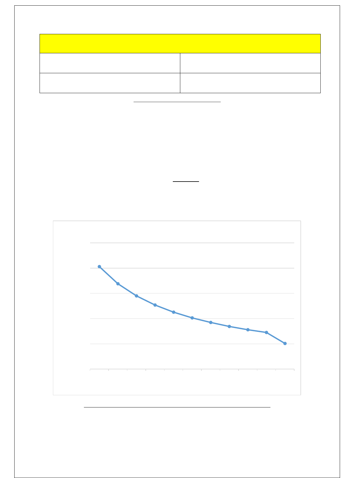
Figure # 10: Graph of Pump Pressure versus Cavitation Number
As visible from the graph above, we can observe a very prominent relation between the pump
pressure and the cavitation number that is subsequently affected from its variation. As the
0
0.0005
0.001
0.0015
0.002
0.0025
50000 60000 70000 80000 90000 100000 110000 120000 130000 140000 200000
Pump Pressure (kPa)
Cavitation Number
Cavitation Number V/S Pump Pressure

29
pressure of the pump is increased, there is a very prominent decrease in the cavitation
number.
Figure # 11: Graph of Volume Flowrate versus Cavitation Number
For the graph displayed above, we can see a prominent relation between the volume flowrate
and the cavitation number that we have experienced and that if the volume flowrate increases,
the cavitation number decreases which is quite visible in the graphical data given in figure #
10 above.
0
0.005
0.01
0.015
0.02
0.025
0.03
6 6.5 7 7.5 8 8.5 9 9.5 10 10.5
Cavitation Number
Volume Flowrate (LPM)
Volume Flowrate vs Cavitation Number

30
Figure # 12: Cavitating a Concrete Block
As visible from the figure given above, the cavitation phenomenon is being tested on a
concrete block of certain thickness and after just targeting the nozzle at the surface of the
block, it can be seen that a significant amount of material has been removed.
Figure # 13: Cavitating a Brick
Similarly, looking at the pictures in above given figure, a very prominent indentation is seen
after directing the cavitating jet on towards the surface of a brick which clearly left a shallow
yet visible indentation depicting that our nozzle is extremely effect.
Chapter 5: Project Management
5.1 Project Plan
The project comprises of various tasks that are assigned to each group member in an equal
manner, to ensure fairness between the members. Each member was given a specific task that
needed to be completed within a certain amount of time.

31
The times and dates listed in the Gantt Chart were followed to ensure consistency and quality
of the work done by the group members.
Table 3 displays the number of tasks done alongside with the number of days it took for that
specific task to be completed.
S. No.
Tasks
Start
End
Duration
1
Ch. 1: Introduction
3/09/2019
6/09/2019
4
2
Ch. 2: Literature
Review
Project Background
7/09/2019
11/09/2019
5
Previous Work
Comparative Study
3
Ch. 3: System
Design
Design Constraints
& Methodology
21/09/2019
1//09/2019
11
Engineering Design
Standards
Theory &
Theoretical
Calculations
Product Subsystems
& Component
Selection
Manufacturing &
Assembly
4
Ch. 4: System
Testing &
Analysis
Experimental Setup,
Sensors & Data
28/11/2019
30/11/2019
3
Results, Analysis &
Discussion

32
5
Ch. 5: Project
Management
Contribution of
Team Members
22/09/2019
24/09/2019
2
Project Execution
Monitoring
Challenges &
Decision Making
Project Bill of
Materials & Budget
6
Ch. 6: Project
Analysis
Impact of
Engineering Solution
11/11/2019
13/11/2019
2
Contemporary Issues
Addressed
7
Ch. 7:
Conclusion &
Recommendation
Conclusion
2/12/2019
3/12/2019
1
Future
Recommendation
8
Design of Prototype
05/10/2019
15/11/2019
45
9
Parts Purchased
8/11/2019
18/2019
10
10
Manufacturing
12/11/2019
22/11/2019
12
11
Testing
28/11/2019
30/11/2019
3
Table # 4: Tasks and their Duration
Table 4 identifies the team members responsible for their respected tasks.
S. No.
Task
Assigned Members
1
Introduction
Sultan & Naif
2
Literature Review
Yazeed & Abdullah
3
System Design
Yazeed & Abdullah
4
Testing and Analysis
Abdullah, Yazeed & Sultan

33
5
Project Management
Naif & Yazeed
6
Project Analysis
Abdullah & Sultan
7
Conclusion and
Recommendation
Naif, Sultan & Abdullah
8
Design
Yazeed
9
Parts Purchased
Sultan & Abdullah
10
Manufacturing
Yazeed & Naif
11
Testing
Everyone
Table # 5: Assigned Members for Each Task
5.2 Contribution of Team Members
Each member’s contribution and their willingness to work was discussed in our first meeting
as a team, and the tasks were divided and agreed upon by each member.
Table # 5 shows how much work each group member contributed, as a rough percentage.
S. No.
Tasks
Assigned Member
Contribution
1
Ch. 1: Introduction
Naif & Sultan
100%
2
Ch. 2: Literature
Review
Project
Background
Abdullah & Yazeed
33%
Previous Work
Abdullah
33%
Comparative
Study
Yazeed
34%
3
Ch. 3: System
Design
Design
Constraints &
Methodology
Yazeed, Sultan & Naif
20%
Engineering
Design Standards
Abdullah
20%
Theory &
Theoretical
Calculations
Abdullah, Yazeed & Naif
20%

34
Product
Subsystems &
Component
Selection
Sultan
20%
Manufacturing &
Assembly
Yazeed
20%
4
Ch. 4: System
Testing &
Analysis
Experimental
Setup, Sensors &
Data
Yazeed
40%
Results, Analysis
& Discussion
Abdullah
60%
5
Ch. 5: Project
Management
Contribution of
Team Members
Naif & Sultain
100%
Project Execution
Monitoring
Challenges &
Decision Making
Project Bill of
Materials &
Budget
6
Ch. 6: Project
Analysis
Impact of
Engineering
Solution
Yazeed
100%
Contemporary
Issues Addressed
7
Ch. 7:
Conclusion &
Recommendation
Conclusion
Abdullah, Yazeed &
Sultan
100%
Future
Recommendation
8
Design of Prototype
Yazeed
50%
Abdullah
50%
9
Parts Purchased
Sultan
20%

35
Yazeed
30%
Abdullah
30%
Naif
20%
10
Manufacturing
Naif
60%
Sultan
40%
11
Testing
Yazeed & Abdullah
100%
Table # 6: Contribution of Tasks
5.3 Project Execution Monitoring
To ensure the continuous progress of the project, regular meetings between the group
members, to discuss the next step, and between the group members and the advisor, to take
approval for said step, needed to be done on a regular basis. In addition to these meeting, we
were asked to hand in progress reports and perform a presentation to explain what we have
done in the project till the date of the presentation. All the dates are listed in table 6 below
Activities and/or Events
Time and Date
Assessment Class
Once a week
Meeting with the group members
Weekly
Meeting with the Advisor
Bi-Weekly
Midterm Presentation
28
th
November, 2019
Finishing Final Prototype
2
nd
December, 2019
Test of the System
2
nd
December, 2019
Final Submission of Report
19
th
December, 2019
Final Presentation
19
th
December, 2019
Table # 7: Dates of Activities and Events
5.4 Challenges and Decision Making
While working in developing our project to its final stages, we incurred some problems
which effected the progress of our project and acted as a hurdle to overcome. However, after
successions of different suggestions and review, they were eventually rectified. The problems
we faced were some of the following:

36
5.4.1: Equipment and Device Problems
Plunger Pump
In order to achieve cavitation phenomenon and to successfully simulate the conditions
on a pilot test scale, we were to select a plunger pump which works on a mechanical
principle of suction and to find a suitable one which had the most modest
specifications was becoming a problem since it was not very commonly available in
the market and required an extensive amount of research and survey.
Nozzle Manufacturing
As the project object relies heavily on how we design our nozzle so it can give rise to
the cavitation phenomenon, the manufacturing was becoming quite a problem since
the nozzle’s overall dimension was intricate and small, it required some very precise
machining and specialized machining shops were a problem to find. Moreover, we
also had to make sure that the design which we agreed on should actually work in the
experimental application for demonstration and testing purposes.
5.4.2: Testing & Safety Issues
Since our project aims to demonstrate the phenomenon of cavitation which could have a very
significant impact in the drilling operations, we were to make sure that safety is kept as a
number one priority since equipment with high pressure applications will be used constantly
and we had to make sure that we take as extra safety precautions and measures as possible.
However, since the cavitation process will be applied on a targeting material for the sake of
demonstration, a proper selection of material and its mounting was very important as we did
not want the pressure from the nozzle to displace or ricochet any material to the spectators or
onlookers.
5.4.3: Design Problems
The most basic and prominent design problems we had were with the selection and designing
of a proper nozzle that could facilitate the cavitation phenomenon and in order to achieve that
we took consideration from many research papers, forums and journals so we can initiate the
designing phase of our nozzle and give it away for manufacturing as soon as possible. This
created a wide range of problems in dimension optimization that in the end after consultations

37
and simulations we agreed on a proper design for the nozzle to be used for demonstration and
production of cavitation.
5.5 Project Bill of Materials & Budget
The table below illustrates the parts we purchased and the amount given to the third party for
manufacturing some of the intricate parts for us. It includes the total amount spent in our
project in Saudi Riyals (SAR).
Table 7 shows the amount of money paid for each part in Saudi Riyals (SAR).
Materials
Cost (SAR)
Plunger Pump
3060
Nozzle Manufacturing
1000
Pressure Gauge
66
Hoses
60
Custom Adapter to Nozzle
250
Acrylic Compartment
600
Trolley
300
Clamps
100
Total Sum
5436
Table # 7: Bill of Materials
Chapter 6: Project Analysis
6.1 Life-Long Learning
Since we were working as a team in the progress of our project, we had one aim completely
firm in our minds and that was to achieve all the goals we had set in the beginning of project.
Of course, in order to achieve that, we were prone to use and utilize some software and
hardware by using our time in a very efficient manner and also to manage all of these things,

38
we had to setup and prescribe a pre-planned schedule which really gave us a boost in every
aspect we worked on and we would like to share some of that experience.
6.1.1: Software Skills:
When designing our prototype, we first referred to some websites online and then test out the
constraints on Solid-Works Simulation. We designed and simulated the necessary
components for our project to guarantee suitable procedure concurring to our needs of
materials that are sufficient enough to withstand our system so that it can run efficiently. It all
went extremely well by the group’s contribution and support since each member was able to
solve an obstacle more rapidly depending on the way they thought. Correspondingly, we
utilized Microsoft Excel to exhibit the charts and graphs displaying our experimentation data.
6.1.2: Hardware Skills:
To conduct a performance test of our system, we had to interact with some of the facilities
provided in our Laboratories which included an IR Thermometer. Having sufficient
background knowledge on using an IR Thermometer we were able to successfully without
additional help. This hardware equipment helped to obtain the experimental data that was
necessary to demonstrate the performance of our system as a whole. Moreover, using
measuring devices like a pressure gauge and flowmeter was also a plus in our project as we
were able to keep track of important parameters like flow-rate and pressure.
6.1.3: Time Management:
Since we had about 3 months of total time to be given to the project, we really needed to
manage time in an efficient manner in order to be ahead of time for predicted problems and
hurdles we thought we would face. Although, we were still falling short of that as days were
passing by, our team really worked on it in every spare time they had available in order to
accomplish a heap of milestone that was set for us.
6.1.4: Project Management:
To carry out the whole schedule of developing our project, we needed a plan to execute and
follow it step by step. By conducting weekly meetings with our team mates, we were able to
assign tasks based on the time one is comfortable and available. This mutual communication

39
and understanding led to a properly managed progress flow related to our project which we
are proud of.
6.2 Impact of Engineering Solutions
6.2.1: Society:
Any project that is for the well fare of the industry that will surely benefit the society of it.
Since, the project will always be aimed towards the betterment of operational efficiency,
effectivity or cost saving without compromising on the quality of the outcome, claims can be
made with pure intention that it would open an opportunity for investors to step in the field to
sponsor such projects which can reach the prosperous stages of development. These
investments will provide a very clear social impact proving the ideas and the skillful youth
which are striving to contribute in achieving one of the objectives of Vision 2030 which is to
increase the public’s investment funds so the people of Saudi Arabia can get benefit and the
needs that any prosperous and developed country would need to survive and compete.
6.2.2: Economy:
0According to the Kingdom’s Vision 2030 objective to improve the GDP and the overall
cost-effectiveness in several different projects, quite prominently in the field of oil and gas,
these technological advancements can play a very supporting role for the future and well-
being prosperity of our country. Since, we as a group and many other technical personnel are
thriving to work hard and devise solutions to improve the quality of operations and save cost,
we think our project could be a very unique initiative towards the contribution of improved
and cost-effective drilling operations. Because, approximate fare for one day of operation at a
typical drilling site in Kingdom can escalate to as much 200,000 U.S. Dollars, little but
prominent advancements can play a very root cause for the cost savings.
6.2.3: Environment:
If we consider our prototype of how it will benefit on an environmental basis, to give an
insight in terms of indirect perspective. It would decrease the cost of fuel used and eventually
lower the pollutants beings produced by the powering up the whole unit when in a drilling
operation. Furthermore, it would serve as a very basic solution in order to decrease bit balling

40
which effectively improves drilling efficiency when down below the borehole subsequently
lowering the power consumption and fuel burnt. These aspects were considered when we
decided to design a cavitation jet nozzle system for drilling bits as it will improve number
associated parameters.
6.3 Contemporary Issues Addressed
Since our prototype or project is still in a condition where many things can go wrong or may
even be a hazard in terms of safety perspective, we ensured that proper precautionary
measures were taken in order to properly operate our mechanism without causing harm to the
environment and operators. Also, some optimization may be required in order to properly
function our mechanism without any pump perturbations and that can resolve quite a number
of problems which will be optimization based if all things are considered where we have to
make sure that a specific range of Reynold’s Number is maintained for a flow to be turbulent
enough to avoid bit balling and improving the drilling operations and to keep the fluid flow in
the cavitation phenomenon range.
Chapter 7: Conclusion & Future Recommendations
7.1 Conclusion
In a nutshell, the senior design project that our team was involved into was
accomplished successfully. However, we did face some problems related to the
manufacturing and designing aspect of the nozzle we agreed and intended to work on but it
was tackled with professionalism and technical knowledge. Moreover, the whole project was
an experience which gave us a lot of knowledge, information, abilities and skills which we
used and also had a chance to enhance them while working on our objective. In the end, we

41
were able to illustrate and represent the cavitation phenomenon by the nozzle we designed
specifically for the purpose of increased rate of penetration which was experimentally tested
on a targeting material.
7.2 Future Recommendations
There have been myriad studies related to cavitation. This research focused on one particular
aspect related to clouds of cavitation bubbles and its impact on the rate of penetration ROP.
The hope is that this work forms a foundation for future research using a cavitating water jet
to erode solid materials at a distance in underwater environments.
The previous research shows that cavitation erosion has the potential to be an effective
cutting mechanism. If a cavitation device that can remotely cut submerged solids without
polluting its surroundings is developed many underwater environments will become safer for
commercial and private use.
Additionally, the cavitation number formula presented in this paper really helps to predict
cavitation occurrence, but it is highly recommended to directly compare the liquid pressure to
the saturated vapor pressure for better and accurate results.
Moreover, we recommend future researchers seeking answers to the following questions:
1. What are the fluid properties of drilling fluid which affect the cavitation phenomena, and
how can cavitating nozzles be designed for optimum performance in these fluids?
2. What are the detailed flow field characteristics of self-resonating cavitating jets, and how
can improved understanding of the jet fluid dynamics be used to develop improved bit nozzle
systems for both existing and higher pressure drilling equipment?
3. How can self-resonating jets be adapted to improve the hole-bottom cleaning action?

42
8. References
1. Saito, Y & Saito, K. (September 2006). Instantaneous Behavior of Cavitation Clouds
at Impingement of cavitating water-jet, Sixth International Symposium on Cavitation,
Retrieved from:
https://pdfs.semanticscholar.org/b4ab/687ed6fb5b27b08bc3638b1e31d03bd62e5d.pdf
2. Li, Z. (October, 2014) Criteria for jet cavitation and cavitation jet drilling,
International Journal of Rock Mechanics and Mining Sciences. Vol: 71, pp: 204-207.
Retrieved from:
https://www.sciencedirect.com/science/article/pii/S1365160914001890
3. Huaizhong, S., Genshing, L & Zhongwei, H. (11 September, 2013). Mechanism of
Hydraulic Pulsed and Cavitating Jet Improving Rop and Application in China
Offishore Drilling. China University of Petroleum. Retrieved from:
https://pdfs.semanticscholar.org/19b0/442e0c70b66fcc1fd74479d58910460ab702.pdf
4. Li, Deng & Kang, Yong & Ding, Xiaolong & Wang, Xiaochuan & Fang, Zhenlong.
(2016). An experimental investigation on the pressure characteristics of high speed
self-resonating pulsed waterjets influenced by feeding pipe diameter. Journal of
Mechanical Science and Technology. 30. 4997-5007. 10.1007/s12206-016-1019-3.
https://www.researchgate.net/publication/309955578_An_experimental_investigation_
on_the_pressure_characteristics_of_high_speed_self-
resonating_pulsed_waterjets_influenced_by_feeding_pipe_diameter
5. Gensheng, L., Huaizhong, S. & Zhiyun, Z. (20 August, 2009). An Experimental Study
on Hydraulic Pulsed Cavitation Jet Drilling in Deep Wells. Retrieved from:
https://www.wjta.org/images/wjta/Proceedings/Papers/2009/G2%20Li.pdf
6. Wang, X., Kang, Y., Zhang, M., Yuan, M. & Li, D. (13
th
November, 2018). The
Effects of the Downstream Contraction Ratio of Organ-Pipe Nozzle on the Pressure
Oscillations of Self-Resonating Waterjets, Energies, Vol: 11, Issue: 11. Retrieved
from:
https://www.mdpi.com/1996-1073/11/11/3137/htm
7. Usta, Onur & Koksal, Cagatay & Korkut, Emin. (2019). An Experimental Study to
Investigate Cavitation Noise and Erosion Characteristics, Using Water Jet Test
Technique. Retrieved from:

