
Aritech Reliance XR Series
Installation and Programming
Guide
P/N 231040 • REV L • ISS 19JUL23
Copyright
© 2023 Carrier Fire & Security
All rights reserved.
This document may not be copied in whole or in part or otherwise reproduced
without prior written consent from Carrier Fire & Security, except where specifically
permitted under US and international copyright law.
Trademarks and patents
Aritech name and logo are trademarks of Carrier Fire & Security
IOS is the registered trademark of Cisco Technology, Inc.
Android, Google and Google Play are registered trademarks of Google Inc.
iPhone, Apple, iTunes are registered trademarks of Apple Inc.
App Store is a service mark of Apple Inc.
Other trade names used in this document may be trademarks or registered
trademarks of the manufacturers or vendors of the respective products.
Manufacturer
Placed on the market by:
Carrier Fire & Security
3211 Progress Drive, Lincolnton, NC, 28092, USA
Authorized EU manufacturing representative:
Carrier Fire & Security B.V.
Kelvinstraat 7, 6003 DH Weert, Netherlands
Warnings and Disclaimers
These products are intended for sale to, and installation by, an experienced security
professional. Carrier Fire & Security cannot provide any assurance that any person or
entity buying its products, including any “authorized dealer,” is properly trained or
experienced to correctly install security related products.
For more information on product warnings, refer to
firesecurityproducts.com/policy/product-warning/ or scan the code.
Contact information
For contact information, point of sale
Customer support
For customer support in Australia, point of sale
Firmware version
This manual was updated for firmware version A59P0000009-42
Installation and Programming Guide iii
Contents
Aritech Reliance XR Series Installation and Programming Guide ........... 1
Important information ........................................................................ vi
Limitation of liability ................................................................................... vi
Product Warnings ....................................................................................... vi
Warranty Disclaimers................................................................................. vii
Disclaimer ................................................................................................. viii
Intended Use ............................................................................................. viii
Advisory messages .................................................................................... viii
Introduction ........................................................................................ 9
System Capacity ...........................................................................................9
Aritech Reliance XR Specifications ...................................................... 10
Product Codes ........................................................................................... 10
Mains power specifications ...................................................................... 10
Power supply specifications...................................................................... 11
General features ....................................................................................... 12
Current Consumption ............................................................................... 13
Output Current Rating .............................................................................. 13
Environmental........................................................................................... 13
Physical Dimensions and Weight .............................................................. 13
Fuses ......................................................................................................... 14
Maintenance ............................................................................................. 14
System Monitoring ................................................................................... 15
SIA and CID reporting code descriptions .................................................. 15
End Of Line (EOL) Resistors ....................................................................... 19
Aritech Reliance XR Pro Layout .......................................................... 20
Aritech Reliance XR Pro Wiring Diagram .................................................. 20
Aritech Reliance XR Pro Terminals............................................................ 21
Aritech Reliance XR Pro LEDs .................................................................... 22
Aritech Reliance XR Layout ................................................................ 23
Aritech Reliance XR Wiring Diagram ......................................................... 23
Aritech Reliance XR LEDs .......................................................................... 25
Aritech Reliance XR Installation.......................................................... 26
Power Requirements ................................................................................ 26
Cable Requirements.................................................................................. 26
Shielding .................................................................................................... 26
Termination Links ..................................................................................... 26
Installing Panel .......................................................................................... 27
Installing Legacy NX Modules ................................................................... 27
Installing Antennas ................................................................................... 28
Enrolling Modules ..................................................................................... 29
Deleting Modules ...................................................................................... 29
iv Installation and Programming Guide
Defaulting Panel ........................................................................................ 30
Defaulting Installer Account ..................................................................... 31
Getting Connected ............................................................................. 32
Account Access.......................................................................................... 32
Method 1: UltraSync+ App ........................................................................ 33
Method 2: Web Server .............................................................................. 39
Method 3: DLX900 Management Software .............................................. 42
Method 4: NXX-1820- Keypad.................................................................. 44
Programming with App / Web Server ................................................. 45
Recommended Items to Change ............................................................... 45
Learning Wireless Zones ........................................................................... 47
Adding a User ............................................................................................ 52
Adding a Keyfob ........................................................................................ 53
Advanced Keyfob Programming ............................................................... 54
Configuring Email Reports ........................................................................ 56
Enabling Push Notifications on Smartphone ............................................ 57
Reporting to a Control Room .................................................................... 62
DLX900 Software ................................................................................ 64
Installing DLX900 ....................................................................................... 64
Upgrading from DL900 .............................................................................. 64
Login to DLX .............................................................................................. 64
Navigating the Main Window ................................................................... 66
Customer Window .................................................................................... 67
Navigating the Menus ............................................................................... 68
Control Panel Menu .................................................................................. 69
Loading Control Panel Defaults ................................................................. 69
Devices Menu ............................................................................................ 70
Device Info ................................................................................................ 71
Download Menu........................................................................................ 72
Reading Data ............................................................................................. 72
Sending Data ............................................................................................. 73
Tools Menu ............................................................................................... 74
Programming with DLX900 ................................................................. 75
Programming Instructions for System Options ........................................ 75
Programming Instructions for Permissions............................................... 79
Programming Instructions for Menus ....................................................... 81
Programming Instructions for Holidays .................................................... 83
Programming Instructions for Users ......................................................... 87
Programming Instructions for Zones ........................................................ 90
Programming Instructions for Custom Zones ........................................... 93
Programming Instructions for Areas ......................................................... 96
Programming Instructions for Schedules .................................................. 99
Programming Instructions for Arm-Disarm ............................................ 103
Programming Instructions for Communicator ........................................ 107
Programming Instructions for UltraSync ................................................ 111
Installation and Programming Guide v
Programming Instructions for Event Lists .............................................. 112
Programming Instructions for Channels ................................................. 114
Programming Instructions for Zone Reporting ....................................... 118
Programming Instructions for System Event Reporting ......................... 121
Programming Instructions for Actions .................................................... 123
Programming Instructions for Action Groups ........................................ 125
Programming Instructions for Scenes .................................................... 127
Programming Instructions for Outputs .................................................. 128
Combining Actions with Schedules ......................................................... 129
Arming and Disarming Your System ..................................................131
Lock Out On 3 Invalid Attempts .............................................................. 131
Arm Your System In Away Mode ............................................................ 131
Arm Your System In Stay Mode .............................................................. 131
Arm Your System in Instant Stay Mode .................................................. 131
Arm Your System In Night Mode ............................................................ 132
Disarm One Or More Areas .................................................................... 132
Activate SOS Feature .............................................................................. 132
Walk Test ................................................................................................ 133
User Reporting ........................................................................................ 133
Appendix 1: System Status Messages ................................................134
Appendix 2: App and Web Error Messages ........................................136
Appendix 3: Advanced Menu Tree .....................................................137
Appendix 4: Troubleshooting ............................................................138
vi Installation and Programming Guide
Important information
Limitation of liability
To the maximum extent permitted by applicable law, in no event will Carrier be liable for
any lost profits or business opportunities, loss of use, business interruption, loss of data, or
any other indirect, special, incidental, or consequential damages under any theory of
liability, whether based in contract, tort, negligence, product liability, or otherwise. Because
some jurisdictions do not allow the exclusion or limitation of liability for consequential or
incidental damages the preceding limitation may not apply to you. In any event the total
liability of Carrier shall not exceed the purchase price of the product. The foregoing
limitation will apply to the maximum extent permitted by applicable law, regardless of
whether Carrier has been advised of the possibility of such damages and regardless of
whether any remedy fails of its essential purpose.
Installation in accordance with this manual, applicable codes, and the instructions of the
authority having jurisdiction is mandatory.
While every precaution has been taken during the preparation of this manual to ensure the
accuracy of its contents, Carrier assumes no responsibility for errors or omissions.
Product Warnings
YOU UNDERSTAND THAT A PROPERLY INSTALLED AND MAINTAINED ALARM/SECURITY
SYSTEM MAY ONLY REDUCE THE RISK OF EVENTS SUCH AS BURGLARY, ROBBERY, FIRE, OR
SIMILAR EVENTS WITHOUT WARNING, BUT IT IS NOT INSURANCE OR A GUARANTEE THAT
SUCH EVENTS WILL NOT OCCUR OR THAT THERE WILL BE NO DEATH, PERSONAL INJURY,
AND/OR PROPERTY DAMAGE AS A RESULT.
THE ABILITY OF INTEROGIX’S PRODUCTS, SOFTWARE OR SERVICES TO WORK PROPERLY
DEPENDS ON A NUMBER OF PRODUCTS AND SERVICES MADE AVAILABLE BY THIRD PARTIES
OVER WHICH ARITECH HAS NO CONTROL AND FOR WHICH ARITECH SHALL NOT BE
RESPONSIBLE INCLUDING, BUT NOT LIMITED TO, INTERNET, CELLULAR AND LANDLINE
CONNECTIVITY; MOBILE DEVICE AND OPERATING SYSTEM COMPATIBILITY; MONITORING
SERVICES; ELECTRONMAGNETIC OR OTHER INTERFERENCE, AND PROPER INSTALLATION
AND MAINTENANCE OF AUTHORIZED PRODUCTS (INCLUDING ALARM OR OTHER CONTROL
PANEL AND SENSORS).
ANY PRODUCT, SOFTWARE, SERVICE OR OTHER OFFERING MANUFACTURED, SOLD OR
LICENSED BY ARITECH, MAY BE HACKED, COMPROMISED AND/OR CIRCUMVENTED AND
ARITECH MAKES NO REPRESENTATION, WARRANTY, CONVENANT OR PROMISE THAT ITS
PRODUCTS (INCLUDING SECURITY PRODUCTS), SOFTWARE, SERVICES OR OTHER OFFERINGS
WILL NOT BE HACKED, COMPROMISED AND/OR CIRCUMVENTED.
ARITECH DOES NOT ENCRYPT COMMUNICATIONS BETWEEN ITS ALARM OR OTHER
CONTROL PANELS AND THEIR WIRELESS OUTPUTS/INPUTS INCLUDING BUT NOT LIMITED
TO, SENSORS OR DETECTORS UNLESS REQUIRED BY APPLICABLE LAW. AS A RESULT, THESE
COMMUNICATIONS MAY BE INTERCEPTED AND COULD BE USED TO CIRCUMVENT YOUR
ALARM/SECURITY SYSTEM.

Installation and Programming Guide vii
THE EQUIPMENT SHOULD ONLY BE OPERATED WITH AN APPROVED POWER ADAPTER WITH
INSULATED LIVE PINS.
DO NOT CONNECT TO A RECEPTACLE CONTROLLED BY A SWITCH.
THIS UNIT INCLUDES AN ALARM VERIFICATION FEATURE THAT WILL RESULT IN A DELAY OF
THE SYSTEM ALARM SIGNAL FROM THE INDICATED CIRCUITS. THE TOTAL DELAY (CONTROL
UNIT PLUS SMOKE DETECTORS) SHALL NOT EXCEED 60 SECONDS. NO OTHER SMOKE
DETECTOR SHALL BE CONNECTED TO THESE CIRCUITS UNLESS APPROVED BY THE LOCAL
AUTHORITY HAVING JURISDICTION.
WARNING: The equipment should only be operated with an approved power adapter with
insulated live pins.
Caution: Risk of explosion if battery is replaced by an incorrect type. Dispose of batteries
according to the instructions. Contact your supplier for replacement batteries.
Warranty Disclaimers
ARITECH HEREBY DISCLAIMS ALL WARRANTIES AND REPRESENTATIONS, WHETHER
EXPRESS, IMPLIED, STATUTORY OR OTHERWISE, INCLUDING ANY IMPLIED WARRANTIES,
THE WARRANTIES OF MERCHANTABILITY OR FITNESS FOR A PARTICULAR PURPOSE.
(USA only) SOME STATES DO NOT ALLOW THE EXCLUSION OF IMPLIED WARRANTIES, SO
THE ABOVE EXCLUSION MAY NOT APPLY TO YOU. YOU MAY ALSO HAVE OTHER LEGAL
RIGHTS THAT VARY FROM STATE TO STATE.
ARITECH DOES NOT MAKE ANY CLAIMS OR WARRANTIES TO YOU OF ANY KIND REGARDING
ANY PRODUCT, SOFTWARE OR SERVICE’S POTENTIAL, ABILITY, OR EFFECTIVENESS TO
DETECT, MINIMIZE, OR IN ANYWAY PREVENT DEATH, PERSONAL INJURY, PROPERTY
DAMAGE, OR LOSS OF ANY KIND WHATSOEVER.
ARITECH DOES NOT REPRESENT TO YOU THAT ANY PRODUCT (INCLUDING SECURITY
PRODUCTS), SOFTWARE, SERVICE OR OTHER OFFERING MAY NOT BE HACKED,
COMPROMISED AND/OR CIRCUMVENTED.
ARITECH DOES NOT WARRANT THAT ANY PRODUCT (INCLUDING SECURITY PRODUCTS),
SOFTWARE OR SERVICE MANUFACTURED, SOLD OR LICENSED BY ARITECH WILL PREVENT,
OR IN ALL CASES PROVIDE ADEQUATE WARNING OF OR PROTECTION FROM, BREAK-INS,
BURGLARY, ROBBERY, FIRE, OR OTHERWISE.
ARITECH DOES NOT WARRANT TO YOU THAT ITS SOFTWARE OR PRODUCTS WILL WORK
PROPERLY IN ALL ENVIRONMENTS AND APPLICATIONS AND DOES NOT WARRANT ANY
PRODUCTS AGAINST HARMFUL ELECTROMAGNETIC INTERFERENCE INDUCTION OR
RADIATION (EMI, RFI, ETC.) EMITTED FROM EXTERNAL SOURCES
ARITECH DOES NOT PROVIDE MONITORING SERVICES FOR YOUR ALARM/SECURITY SYSTEM
(“MONITORING SERVICES”). IF YOU ELECT TO HAVE MONITORING SERVICES YOU MUST
OBTAIN SUCH SERVICE FROM A THIRD PARTY AND ARITECH MAKES NO REPRESENTATION
OR WARRANTY WITH RESPECT TO SUCH SERVICES INCLUDING WHETHER OR NOT THEY
WILL BE COMPATIBLE WITH THE PRODUCTS, SOFTWARE OR SERVICES MANFUFACTURED,
SOLD OR LICENSED BY ARITECH.

viii Installation and Programming Guide
Disclaimer
THE INFORMATION IN THIS DOCUMENT IS SUBJECT TO CHANGE WITHOUT NOTICE.
CARRIER ASSUMES NO RESPONSIBILITY FOR INACCURACIES OR OMISSIONS AND
SPECIFICALLY DISCLAIMS ANY LIABILITIES, LOSSES, OR RISKS, PERSONAL OR OTHERWISE,
INCURRED AS A CONSEQUENCE, DIRECTLY OR INDIRECTLY, OF THE USE OR APPLICATION OF
ANY OF THE CONTENTS OF THIS DOCUMENT. FOR THE LATEST DOCUMENTATION,
CONTACT YOUR LOCAL SUPPLIER OR VISIT US ONLINE AT
WWW.UTCFIREANDSECURITY.COM.
This publication may contain examples of screen captures and reports used in daily
operations. Examples may include fictitious names of individuals and companies. Any
similarity to names and addresses of actual businesses or persons is entirely coincidental.
The illustrations in this manual are intended as a guide and may differ from your actual unit
as Aritech Reliance XR is continually being improved.
Intended Use
Use this product only for the purpose it was designed for; refer to the data sheet and user
documentation. For the latest product information, contact your local supplier or visit us
online at www.utcfireandsecurity.com.
The system should be checked by a qualified technician at least every 3 years and the
backup battery replaced as required.
Advisory messages
Advisory messages alert you to conditions or practices that can cause unwanted results.
The advisory messages used in this document are shown and described below.
WARNING: Warning messages advise you of hazards that could result in injury or loss of
life. They tell you which actions to take or to avoid preventing the injury or loss of life.
Caution: Caution messages advise you of possible equipment damage. They tell you which
actions to take or to avoid preventing damage.
Note: Note messages advise you of the possible loss of time or effort. They describe how to
avoid the loss. Notes are also used to point out important information that you should read

Installation and Programming Guide 9
Introduction
The Aritech Reliance XR is an advanced intrusion panel with native IP reporting to
UltraSync cloud. It has been designed for smartphone access to allow professional
installer programming, and end-users’ convenient access.
With large expansion capabilities, multi-area mode, wireless expansion, advanced user
permissions, advanced schedules, and smart home features, the Aritech Reliance XR is
suitable for residential and small commercial applications.
The system can be quickly programmed using drop-down menus in the UltraSync+ app.
Programming is possible using a web browser or DLX900 desktop software.
All zones, areas, lists, groups, outputs, schedules, permission profiles, and defaults can
be assigned a text name to make it easy to program and maintain.
When installed with the NXX-1820- touchscreen keypad, menus appear as plain text on
a clear 3.5” screen with access to all programming features.
System Capacity
Feature
Aritech Reliance XR
Aritech Reliance XR Pro
On-board zones
Zone doubled
4
8
8
16
Wireless Zones
16
176
Wireless Receiver
63-bit and
80plus encrypted devices
63-bit and
80plus encrypted devices
Areas
4
8
Users
40
256
Max Keyfobs
8
16
Max Tablets
4
4
Max Expander Modules
incl Keypads
32 Total
[16 Keypads max]
32 Total
[24 Keypads max]
IP Communicator
Built-in
Built-in
UltraSync+ app
Yes
Yes

10 Installation and Programming Guide
Aritech Reliance XR Specifications
Product Codes
Product
Main description
Additional description
NXX-8-W-AU
Aritech Reliance XR Pro
Aritech Reliance XR Pro Panel /w 8 Hardwired
Zones, 433/433MHz 80 Bit, Home Automation,
metal housing, tamper switch
NXX-4-W-AU
Aritech Reliance XR
Aritech Reliance XR Panel /w 4 Hardwired
Zones, 433/433MHz 80 Bit, metal
housing, tamper switch
NXX-8-W-BO-AU
Aritech Reliance XR Pro, Board Only
Aritech Reliance XR Pro Panel /w 8
Hardwired Zones, 433/433MHz 80
Bit, 921.42MHz
NXX-4-W-BO-AU
Aritech Reliance XR,
Board Only
Aritech Reliance XR Panel /w 4 Hardwired
Zones, 433/433MHz 80 Bit, board only
NXX-4GWF
4G & WiFi Router Module
Dual SIM 4G cellular and WiFi router
module
NXX-1820
Touchscreen Keypad
3.5” Touchscreen keypad, multilingual
RF-EV1016-K4
Wireless Mirror Optic PIR Two Way
80plus
RF-4041-07-2
4-button Keyfob Two Way, 433Mhz
80plus
RF-DC101-K4
Wireless Door Window Switch,
433MHz 80plus
RF-1110-07-1
Micro Door Window Switch Two
Way, 433MHz 80plus White
RF-EV1012PI-K4
Wireless Mirror Optic Pet Immune
PIR Two Way 80plus
RF-7120-07-1
"Designer" Stand-alone Wireless
Indoor Siren (800mAh)
RF-7220-07-1
"Designer" Stand-alone Wireless
Outdoor Siren
BS7201-N
Lithium Battery for RF-7220-07-1
Mains power specifications
Mains input voltage
230 Vac +10%, −15%, 50 Hz ±10%
Current consumption at 230 Vac
240 mA max.
Transformer output :
16.3 VAC 24 VA
16.3 VAC 48 VA

Installation and Programming Guide 11
Power supply specifications
Power supply type
For indoor use inside the supervised premises
Power supply voltage
13.8 VDC +/- 0.4 V
Power supply current
2 A max. at 13.8 VDC +/- 0.4 V
Main board consumption
Aritech Reliance XR Pro
130 mA at 13.8 VDC +/- 0.4 V
Aritech Reliance XR
130 mA at 13.8 VDC +/- 0.4 V
Maximum system current available
Aritech Reliance XR Pro
Aritech Reliance XR
2000 mA at 13.8 VDC +/- 0.4 V
2000 mA at 13.8 VDC +/- 0.4 V
Auxiliary power output (AUX. POWER)
Aritech Reliance XR Pro
Aritech Reliance XR
13.8 VDC +/- 0.2 V, 1 A max.
13.8 VDC +/- 0.2 V, 1 A max.
Battery power output (BAT)
Aritech Reliance XR Pro
Aritech Reliance XR
13.8 VDC +/- 0.2 V, 350 mA max.
13.8 VDC +/- 0.2 V, 350 mA max.
Battery type
Lead acid rechargeable
7.2 Ah 12 V nominal
Minimum voltage
9.45 VDC
Maximum voltage at power supply,
auxiliary power output and battery
power output
14.5 VDC
Battery low condition
11.3 Vdc to 11.8 Vdc
Battery disconnect voltage
9.77 Vdc
Maximum ripple voltage V, p-p
200 mV typical, 400 mV max.

12 Installation and Programming Guide
General features
Code combinations
Aritech Reliance XR Pro
Aritech Reliance XR
From 10,000 (4 digits) to 100,000,000 (8 digits)
From 10,000 (4 digits) to 100,000,000 (8 digits)
Maximum user number:
Aritech Reliance XR Pro
Aritech Reliance XR
256
40
User Permissions
128
Onboard zones
Aritech Reliance XR Pro
Aritech Reliance XR
8 (default); 16 if zone doubling enabled.
4 (default); 8 if zone doubling enabled.
Maximum zone number:
Aritech Reliance XR Pro
Aritech Reliance XR
176
24
Additional inputs
Aritech Reliance XR Pro
Aritech Reliance XR
1: box tamper
1: box tamper
End-of-line resistor
820 Ω (2-wire smoke)
3.3 kΩ, 4.1 kΩ, 4.7 kΩ (alarm)
3.74 kΩ, 6.98 kΩ (zone doubling)
Onboard outputs:
Aritech Reliance XR Pro
Aritech Reliance XR
4 programmable outputs, bell, and smoke
3 programmable outputs, and bell
Maximum output number
32
Maximum action number
256, main panel supports 32 actions, each output module adds 32
actions, seven output modules will provide a maximum of 256
actions
Areas:
Aritech Reliance XR Pro
Aritech Reliance XR
8
4
Maximum keypad
Aritech Reliance XR Pro
Aritech Reliance XR
24
16
Maximum expander modules (incl keypads
and tablets)
32
Non-volatile Memory
Event log capacity
Data retention (log, program settings)
1024
10 years
Ethernet connection (IP only)
Supported standard
Speed
Duplex
Cabling
IEEE 802.3u
10BASE-T or 100BASE-TX
Half-duplex and full-duplex
FTP (foiled twisted pair) Cat 5e cable or better
Aritech Reliance XR bus
Type
Capacity
Range
Recommended Cable
4 wire RS485 bus
High common mode tolerance (25V)
Up to 32 devices
800m
Belden 7201A, 3107A, 9842, or exact equivalent 2 pair twisted
shielded cable designed for RS485 (see "
Cable Requirements" on page 26)

Installation and Programming Guide 13
Current Consumption
Product
Main description
Current Consumption
(non-alarm)
Current Consumption
(alarm)
NXX-8-WZ-AU
Aritech Reliance XR Pro
130 mA typical
130 mA typical
NXX-4-W-AU
Aritech Reliance XR
130 mA typical
130 mA typical
NXX-1820
Touchscreen keypad
100 mA typical,
40 mA in idle mode
175 mA max with
sounder and screen on
max brightness
Output Current Rating
Aritech Reliance XR Pro / Aritech Reliance XR (AU)
Output
Total Max Output Current
24 VA
Transformer
48 VA
Transformer
Combined J2 BELL+, J2 AUX+ (Smoke),
and J7 AUX+ (Outputs)
650 mA max at
13.8 VDC
1.6 A max at
13.8 VDC
Combined J2 POS (XR Bus), and J3 POS (NX Bus)
Environmental
Operating temperature
−10 to +55°C
Humidity
95% non-condensing
IP protection grade
IP30
Physical Dimensions and Weight
Product
Main description
Dimensions (HxWxD)
Weight (g)
NXX-8-WZ-AU
Aritech Reliance XR Pro /w metal enclosure
and tamper
292 x 291 x 91 mm
(enclosure only)
437 x 291 x 91 mm
(with antennas)
2075 g
NXX-4-W-AU
Aritech Reliance XR /w metal enclosure and
tamper
214 x 232 x 94 mm
(enclosure only)
359 x 232 x 94 mm
(with antennas)
1435 g
NXX-8-WZ-BO-AU
Aritech Reliance XR Pro, board only
273 x 89 x 25 mm
210 g
NXX-4-W-BO-AU
Aritech Reliance XR,
board only
192 x 89 x 25 mm
155 g
NXX-1820
Touchscreen keypad
18 x 82 x 125 mm
150 g

14 Installation and Programming Guide
Fuses
Battery
4 A, resettable
12 V aux (combined for J2 BELL+, J2 AUX+, J7 AUX+)
3 A, resettable
System LAN (combined for J2 POS, J3 POS)
2 A, resettable
Maintenance
No regular maintenance needed. System will report servicing when necessary.

Installation and Programming Guide 15
System Monitoring
The system provides monitoring for the following items.
Monitoring function
Message
Cause
AC Mains
Mains fail
Loss of external power supply [1]
Battery
Battery low
Battery low voltage [1]
Battery test fail
Exhausted battery
Battery charger fail
Fuse/power output fail
Output overload
Power outputs
Fuse/power output fail
Exhausted fuse
Fuse loss
Short circuit
Overload
Power supply
Power unit/power output fail
Power unit failure
Overvoltage
Tampers
Device tamper
Device sabotage
SIA and CID reporting code descriptions
CID Code
Class
SIA Code
Event
E110
Alarm
FA
Fire alarm
R110
Alarm restore
FR
Fire alarm restore
E120
Alarm
PA
24 hour alarm
R120
Alarm restore
PR
24 hour alarm restore
E130
Alarm
BA
Burg alarm
R130
Alarm restore
BR
Burg alarm restore
E570
Bypass
B
Bypass
R570
Bypass
U
Bypass restore
E383
Zone tamper
TA
Tamper
R383
Zone tamper
TR
Tamper restore
E380
Trouble
T
Trouble
R380
Trouble
R
Trouble restore
E384
Sensor batt
XT
Sensor low battery
R384
Sensor batt
XR
Sensor low battery restore
E381
Sensor lost
S
Wireless supervision
R381
Sensor lost
R
Wireless supervision restore
E200
Sensor lost
SS
Fire supervision
R200
Sensor lost
SR
Fire supervision restore
E391
Sensor lost
NA
Zone activity supervision
R391
Sensor lost
NS
Zone activity supervision restore
E378
Alarm
BG
Cross zone initial trip
R378
Alarm
BR
Cross zone initial trip restore
E389
Sensor batt
AS
Fire maintenance alarm
R389
Sensor batt
AN
Fire maintenance alarm restore
E426
Access alarm
DL
Door propped

16 Installation and Programming Guide
R426
Access alarm
DH
Door propped
E423
Access alarm
DF
Door forced
R423
Access alarm
DR
Door forced
E611
Test
TP
Start walk test zone
E389
Test
TE
End zone test
E611
Test
TP
Walk test zone passed
E389
Test
TE
Walk test zone failed
E383
Zone tamper
TA
Tamper
R383
Zone tamper
TR
E139
Alarm
BA
E130
Alarm
BV
E129
Alarm
HA
E120
Alarm
HV
E129
Alarm
PA
E120
Alarm
HV
E115
Manual alarm
FA
Manual fire
E100
Manual alarm
MA
Manual medical
E123
Manual alarm
PA
Manual audible panic
E122
Manual alarm
HA
Manual silent panic
E124
Manual alarm
HA
Duress
E461
Tamper
JA
Keypad lockout
E137
Tamper
TA
Box tamper
R137
Tamper
TR
Box tamper restore
E301
Ac power
AT
Mains fail event
R301
Ac power
AR
Mains fail event restore
E302
Battery power
YT
Battery low event
R302
Battery power
YR
Battery low event restore
E312
Aux power
YI
Over current
R312
Aux power
YJ
Over current restore
E320
Siren trouble
YA
Siren tamper
R320
Siren trouble
YH
Siren tamper restore
E351
Telephone cut
LT
Telephone fault
R351
Telephone cut
LR
Telephone fault restore
E354
Comms fail
YC
Communication failure
R354
Comms fail
YK
Communication failure restore
E333
Expander trouble
ET
Device failure
R333
Expander trouble
ER
Device failure restore
E401
Open
OP
Open
R401
Open
CL
Close
E401
Open
OP
First open
R401
Open
CL
Last close
E451
Open
CG
Partial close
E374
Recent close
EE
Exit error
E459
Recent close
CR
Recent close
E406
Cancel
AB
Abort
E406
Cancel
OC
Cancel
E602
Automatic test
RP
Automatic test
E601
Test
RX
Manual test
E625
Local program
JT
Clock changed
E627
Local program
LB
Start local program

Installation and Programming Guide 17
E628
Local program
LX
End local program
E627
Remote program
RB
Start remote program
E628
Remote program
RS
End remote program
E607
Test
TS
Start walk test mode
R607
Test
TE
End walk test mode
E466
Recent close
Technician arrival
R466
Recent close
YZ
Technician left
E310
System troubles
FT
Ground fault
R310
System troubles
FR
Ground fault restore
E606
Alarm
LF
Start listen in
R606
Alarm
LE
End listen in
E451
Open
OK
Early opening (disarmed before opening
window)
R452
Open
CJ
Late closing (armed after the opening window)
E453
Open
OI
Fail to open
E454
Open
CI
Fail to close
E344
System troubles
XQ
Wireless jam
R344
System troubles
XH
Wireless jam restore
E414
System troubles
System shut down
R414
System troubles
RR
System turn on
E323
Access
RC
Output activated
R323
Access
RO
Output restored
E531
Expander trouble
SC
Device enrolled
E422
Access
DG
User activated output
E422
Access
DG
Door access
E421
Access
DV
Door access denied
E305
Comms fail
YW
Watchdog reset
R451
Open
OP
Partial open
E401
Abortable alarm
BC
Abort alarm
E102
Access
JK
Guard tour fail
E641
Test
NA
Activity monitor fail
E422
Access
DG
Valid code entered
E421
Access
DP
Valid code out schedule
E421
Access
DV
Valid code void
E421
Access
DV
Valid code lost
E421
Access
DV
Valid code expired
E628
Access
RU
Remote program fail
E102
Access
CL
Man down rearm
E305
Expander trouble
RR
Powerup
R305
Expander trouble
RR
Powerup restore
R601
Test
RX
Manual test restore
E452
Open
OJ
Late opening
R451
Open
CK
Early closing
E532
Device bypass
UB
Device bypass
E531
Device bypass
UU
Device unbypass
E304
Checksum fault
YF
Checksum failure
R304
Checksum fault
YG
Checksum failure restore
E338
Battery power
YT
Expander low battery
R338
Battery power
YR
Checksum failure restore
E337
Battery power
YT
DC fail
R337
Battery power
YR
DC fail restore

18 Installation and Programming Guide
E609
Video
Video event
E351
Comms fail
LT
IP path fault
R351
Comms fail
LR
IP path fault restore
E458
Open
Geo fence 1 entered
R458
Open
Geo fence 1 exited
E458
Open
Geo fence 2 entered
R458
Open
Geo fence 3 exited
R351
System troubles
LR
Power supply fault
R351
System troubles
LR
Power supply fault restore

Installation and Programming Guide 19
End Of Line (EOL) Resistors

20 Installation and Programming Guide
Aritech Reliance XR Pro Layout
Aritech Reliance XR Pro Wiring Diagram
Installation and Programming Guide 21
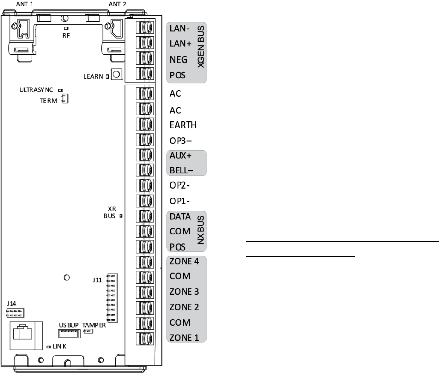
Aritech Reliance XR Pro Terminals
Top to bottom:
• Antenna 1 – after the board is installed in
the metal enclosure, insert the antenna
with the corresponding icon.
• Antenna 2 – after the board is installed in
the metal enclosure, insert the antenna
with the corresponding icon.
• LAN-, LAN+, NEG, POS – terminals for
Aritech Reliance XR RS485 bus.
• S1 LEARN – enrollment button, hold
down for 3s to activate automatic device
enrollment feature. Hold down while
powering up to reset the "installer"
account to master installer user type with
9713 PIN.
• TERM – term link for Aritech Reliance XR
RS485 bus. A TERM link should be
installed on the two furthest devices.
• EARTH, AC, AC – connect transformer
(16VAC 1.5A) to terminals for power.
• - BLACK, + RED – connect leads to 12V
Sealed Lead Acid backup battery.
• BELL+, BELL- – supervised output for
connecting an external 12V siren or
internal piezo screamer.
• DATA, COM, POS – NetworX 3-wire bus
for legacy modules and keypads.
• SMOKE-, AUX+ – supports two or four
wire smoke detectors, for 2-wire smoke
detectors the panel will drop power to
the SMOKE- terminal to perform smoke
alarm verification.
• COM, AUX+ – terminal for aux power to
zones.
• ZONE 1 to 8, COM – terminals to connect
to zones. Supports single EOL, zone
doubling, and dual EOL tamper
monitoring.
• J14 – Ethernet WAN link header must be
fitted if no communicator module is
installed and must be removed to
accommodate communicator module.
• J11 – terminal to connect communicator
module to Aritech Reliance XR.
• Ethernet – connect Ethernet cable to
RJ45 socket to provide internet
connectivity to Aritech Reliance XR.
• J13 USBUP – 5-pin connector used to
upgrade and program Aritech Reliance XR
with USBUP tool.
• TAMPER – connect to panel box tamper.
• AUX+ – terminal for auxiliary power.
• OUTPUT 4 – open collector output
switches to ground, follows “armed”
state at default.
• OUTPUT 3 – open collector output
switches to ground, follows “ready” state
at default.
• OUTPUT 2 – open collector output
switches to ground, follows “any alarm”
at default.
• OUTPUT 1 – open collector output
switches to ground, follows “any siren” at
default.

22 Installation and Programming Guide
Aritech Reliance XR Pro LEDs
Top to bottom:
• D5 RF – red LED blinks when message
sent / received from a 63bit / 80plus
transmitter.
• D7 LAN – green LED is lit when connected
to UltraSync, remains off when not
connected to UltraSync.
• D4 LEARN – red LED blinks slowly during
auto enrollment, blinks quickly during
manual enrollment.
• D3 XR BUS – red LED blinks to indicate
Aritech Reliance XR bus is available.
• D1 ETHERNET – red LED is lit when
Ethernet cable is connected to WAN port,
blinks when data is sent or received, and
is off when cable is disconnected or J14
connector is removed.
If 4G / WiFi router module is installed,
LED is lit when panel has established
connection to the module, and blinks
when panel is communicating with the
module.
Check “Connection Status” web page to
verify connection to UltraSync.

Installation and Programming Guide 23
Aritech Reliance XR Layout
Aritech Reliance XR Wiring Diagram
24 Installation and Programming Guide
Aritech Reliance XR Terminals
Top to bottom:
• Antenna 1 – after the board is installed in
the metal enclosure, insert the antenna
with the corresponding icon.
• Antenna 2 – after the board is installed in
the metal enclosure, insert the antenna
with the corresponding icon.
• LAN-, LAN+, NEG, POS – terminals for
Aritech Reliance XR RS485 bus.
• S1 LEARN – enrollment button, hold
down for 3s to activate automatic device
enrollment feature. Hold down while
powering up to reset the "installer"
account to master installer user type with
9713 PIN.
• TERM – term link for Aritech Reliance XR
RS485 bus. A TERM link should be
installed on the two furthest devices.
• AC, AC, EARTH – connect transformer
(16VAC 1.5A) to terminals for power.
• OUTPUT 3- – open collector output
switches to ground, follows “ready” state
at default.
• - BLACK, + RED – connect leads to 12V
Sealed Lead Acid backup battery.
• AUX+, BELL- – supervised output for
connecting an external 12V siren or
internal piezo screamer.
• OUTPUT 2- – open collector output
switches to ground, follows “any alarm”
action at default.
• OUTPUT 1- – open collector output
switches to ground, follows “any siren”
action at default.
• DATA, COM, POS – NetworX 3-wire bus
for legacy modules and keypads.
• ZONE 1 to 4, COM – terminals to connect
to zones. Supports single EOL, zone
doubling, and dual EOL tamper
monitoring.
• J14 – Ethernet WAN link header must be
fitted if no communicator module is
installed and must be removed to
accommodate communicator module.
• Ethernet – connect Ethernet cable to
RJ45 socket to provide internet
connectivity to Aritech Reliance XR.
• J13 USBUP – 5-pin connector used to
upgrade and program Aritech Reliance XR
with USBUP tool.
• TAMPER – connect to panel box tamper.
• J11 – terminal to connect communicator
module to Aritech Reliance XR.
Installation and Programming Guide 25
Aritech Reliance XR LEDs
Top to bottom:
• D5 RF – red LED blinks when message
sent / received from a 63bit / 80plus
transmitter.
• D7 ULTRASYNC LAN – green LED is lit
when connected to UltraSync, remains
off when not connected to UltraSync.
• D4 LEARN – red LED blinks slowly during
auto enrollment, blinks quickly during
manual enrollment.
• D3 XR BUS – red LED blinks to indicate
Aritech Reliance XR bus is available.
• D1 ETHERNET – red LED is lit when
Ethernet cable is connected to WAN port,
blinks when data is sent or received, and
is off when cable is disconnected or J14
connector is removed.
If 4G / WiFi router module is installed,
LED is lit when panel has established
connection to the module, and blinks
when panel is communicating with the
module.
Check “Connection Status” web page to
verify connection to UltraSync.
26 Installation and Programming Guide
Aritech Reliance XR Installation
Power Requirements
The Aritech Reliance XR range of products are to be only powered from an approved
Australian power unit source.
The Aritech Reliance XR is designed to be used with a 16 VAC 1.5 Amp 24 VA transformer
which is included with Aritech Reliance XR panel kits. If more current is required, upgrade
to a 16 VAC 3 Amp 48 VA transformer and/or add NXG-320 Smart Bus Power Supplies.
Cable Requirements
The system RS-485 communication bus is used to connect keypads, input, and output
expanders to the Aritech Reliance XR.
• Only VW-1 rated cable is to be used for installation of these products.
• 800 m total cable run on system.
• Max. 800 m from remote device to Aritech Reliance XR control panel.
• Max. 32 devices plus panel.
Shielding
The shielding of all shielded cables used in the system should only be connected at one side
to one common earthing point in a building. If a shielded LAN cable is routed via more than
one plastic device, the shielding from incoming and outgoing cable must be connected.
Termination Links
Put a jumper across TERM on the panel and the furthest device to ensure correct RS-485
termination and avoid communication issues with signal reflection, etc.

Installation and Programming Guide 27
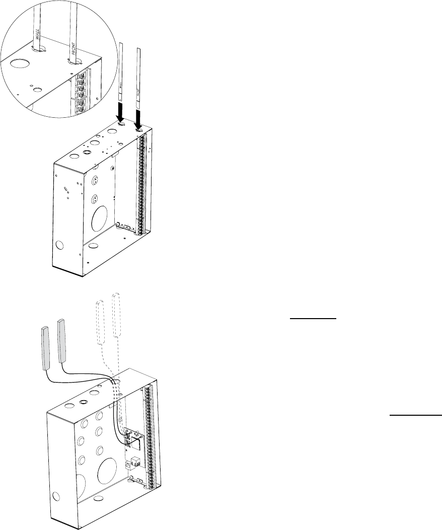
Installing Panel
1. The Aritech Reliance XR should be located away from damp areas (e.g. bathrooms,
kitchens), away from sources of heat, dust or interference (e.g. air conditioners,
washing machines, dryers, refrigerators) and away from external walls.
2. The metal enclosure should be installed with the door opening from the top to bottom.
3. Guides are cut into the enclosure to hold the
panel, two on the top and two on the bottom. Two
plastic brackets are pre-installed on the Aritech Reliance
XR. Slide the panel into the guides as shown in the
diagram. The terminal strip should face towards you
once installed.
4. A plastic strap is provided to allow the door to form a
temporary surface to hold light parts.
Installing Legacy NX Modules
Inside the enclosure there are several 2-holed insertion
points. These allows for either vertical or horizontal
placement of legacy NX modules. Each insertion point has
a larger hole and a smaller hole.
1. The black plastic PCB guides feature a groove to hold
an expansion module. The end with the half-moon
protrusion fits into the larger hole. The smaller hole is for
the screw.
2. Place the first black plastic PCB guide in the top
insertion point, groove facing downward. The half-moon
protrusion will be in the large hole. It does not require
force to insert. Insert one of the provided screws into the
smaller hole (from inside the enclosure) to secure it in
place. A screwdriver should reach through the groove that
runs the length of the guide to tighten the screw. The
second PCB guide should be positioned opposite the first
(groove facing up) and placed in the lower insertion point,
using the same procedures described above. Once
mounted, screw it in securely.
3. The NX module should slide freely in the grooves of
both guides.
28 Installation and Programming Guide
Installing Antennas
Several antennas may be provided depending on the model purchased. These include:
• Multi-antennas for ITI 63-bit, ITI 80plus.
• 3G/4G antennas for WiFi/cellular module
• WiFi antennas for WiFi/cellular module
Wireless Sensor Antennas
If two antennas have been provided:
1. Install panel into metal enclosure.
2. Install antennas vertically for best performance.
3. Each antenna is keyed (shaped differently) and
labelled. Antennas are reasonably flexible but do not
apply excessive force. Match the antenna to the
shape molded on the plastic bracket and push to
insert.
4. The line printed on each antenna will disappear
when fully inserted.
5. Remove antennas before attempting to remove
panel.
6. Antennas can be tampered monitored be enabling
Advanced – General Options – Antenna Tamper.
4G Cellular and WiFi Router Module Antennas
If the optional 4G Cellular and WiFi Router Module
has been installed, a single set of antennas should be
connected to “MAIN” on the module. The antennas
should be installed vertically, and as high up as
possible.
The module includes MIMO wireless technology to
improve reception of 3G/4G and WiFi wireless
signals. This requires the installation of a second set
of antennas to “DIV” on the 4G/WiFi Router Module.
The second set of antennas will perform best when
separated from the MAIN antennas by at least 20cm.
Installation and Programming Guide 29
Enrolling Modules
New devices such as zone expanders, wireless zone expanders, output expanders, smart
power supplies, and keypads need to be enrolled so they can be programmed and
supervised.
The enrollment procedure discovers the serial number of the new device and adds it to the
device database in the panel.
To enroll a module:
1. Press and hold the LEARN button until the LED next to the button blinks, then release
button.
2. The panel is now in automatic enrollment mode and will search for new devices.
3. The D5 LED will stop blinking to indicate enrollment mode is finished.
4. Proceed to programming the system and the additional devices.
Enrollment can also be initiated:
• Using the NXX-1820 keypad: press Menu – [Installer PIN] – [ENTER] – Program –
Devices – System Devices – Control – Enroll Function – 0 = Inactive – Automatic
Enroll.
• Using the Aritech Reliance XR Web Server: click the Advanced Menu, click Devices –
System – Control – Enroll Function – Automatic Enroll – Save.
• Using DLX900: click Devices – Device Info – Auto Enroll.
Deleting Modules
Devices such as zone expanders, output expanders, and keypads can be removed from the
system by deleting the serial number from the device database.
To delete a module:
1. On the keypad press Menu – [Installer PIN] – [ENTER] – Program – Devices.
2. This menu will be displayed:
1. System Devices
1. Control
2. Keypad
3. Zone Exp
4. Output Exp
5. Power Supply
2. ARITECH Transmitters
1. Transmitter Number
2. Serial Number
30 Installation and Programming Guide
3. User
4. Options
5. Scene
3. Tablet Keypads
1. Name
2. Serial Number
3. Area Group
4. Keypad Options
3. Select the category and type. For example, to remove a keypad touch System Devices -
Keypad.
4. Touch Device UID (Serial).
5. Touch the serial number displayed.
6. Touch Clear.
7. Touch OK.
8. The device has now been removed.
Deleting devices can also be done:
• Using the Aritech Reliance XR Web Server: click the Advanced Menu, click Devices,
find the device to be removed, delete the serial number, click Save.
• Using DLX900: click Devices – Device Info, select the device, then click “Remove
Device”.
Defaulting Panel
Panel can be reset to factory settings by performing the steps below. This will delete all
programming including enrolled devices, users, and panel settings. An authorized installer
PIN is required.
Panel can be defaulted using an NXG-1820 keypad:
1. Tap MENU.
2. Enter installer PIN.
3. Tap Program.
4. Tap Default.
5. Tap All.
Installation and Programming Guide 31
Alternatively, from the web server:
1. Log in to the web server as installer.
2. Click Advanced.
3. Click Shortcut.
4. Enter 910.910
5. Press OK.
6. Log out of panel
DLX900 can load default configuration if it can connect to the panel (requires valid
download access code).
1. Open DLX900.
2. Connect to the desired panel.
3. Click Control Panel – Default control data from – Factory defaults.
4. Click Yes – all exiting programming for currently selected customer will be replaced with
factory settings.
5. Click Send All Data.
6. Before disconnecting ensure Download Access Code, Web Access Code, and Installer
PIN are set. Otherwise, you may not be able to reconnect.
Defaulting Installer Account
The installer PIN can be reset to factory default if physical access is available:
1. Disconnect power.
2. Hold down the LEARN button on the panel.
3. Connect power.
4. Continue holding the LEARN button for 10 seconds.
5. Release LEARN button.
6. Installer PIN will be reset to factory default.

32 Installation and Programming Guide
Getting Connected
Once your devices have been cabled and installed, there are four (4) ways to connect to the
Aritech Reliance XR system to perform programming:
Method 1: via UltraSync+ app – this provides access to the built-in Web Server
via a smartphone app.
Method 2: via built-in Web Server – All features can be accessed from a web
browser via drop-down and click-through menus. No software installation is
required. This allows access to most accessed features for basic programming.
Method 3: via DLX900 Management Software – All features can be
programmed using a PC with Microsoft Windows 7, 8 and 10. DLX900 allows
easier programming of complex sites as the graphical interface can show all
options from multiple menus simultaneously.
Method 4: via on-site keypad - The NXX-1820- touchscreen offers a
programming menu for full system configuration. Refer to the NXX-1820-
Installation Manual. The Aritech Reliance XR Reference Guide will assist you in
navigating the menus.
Account Access
Note: Installer Account Disabled When Armed
If a non-engineer account arms the system at any time, engineer accounts will not be able
to log in, any current program mode will end, and this will be recorded in the event log. Ask
the end-user to disarm the panel and leave it disarmed so you can log in to program it.
Note: Remote Access May Require Level 2 User Authorization
Two remote access features “Enable Web Program” and “Always Allow DLX900” require an
authorized master (Level 2) user to enter their PIN code on an NXX-1820- keypad before
remote programming can be performed.
If either “Enable Web Program” or “Always Allow DLX900” have been disabled, ask a
Master User to press Menu, enter their PIN code on a keypad, then Settings. The panel will
now be in Program Mode, and you can use an engineer (Level 3) user such as “installer” to
perform programming via the web page, app, or DLX900.

Installation and Programming Guide 33
Method 1: UltraSync+ App
UltraSync+ is a smartphone app that allows you to:
• Check the status of your system
• Arm and Disarm areas
• Bypass zones
• Manage users
• Perform system programming
Access from the app is disabled by default for security. To allow access these settings must
be enabled on your Aritech Reliance XR system:
• Web Access Code
It permits remote access from the UltraSync+ app. Set it to 00000000 to prevent the
app from connecting.
• Username and PIN code
The UltraSync+ app requires any username and PIN code to log in to the system and
display features available to that user.
Set Web Access Code and change installer PIN code
To enable the UltraSync+ app:
1. On the NXX-1820- keypad press Menu – [PIN] – [ENTER] – Program – scroll down to
UltraSync – Web Access Passcode.
2. Enter a new 8-digit Web Access Passcode.
Change installer PIN code:
1. On the NXX-1820- keypad press Menu – [PIN] – [ENTER] – Users – Add. Modify
2. Enter a new PIN code.

34 Installation and Programming Guide
Connect to Aritech Reliance XR via UltraSync+ app
UltraSync+ is an app that allows you to control your Aritech Reliance XR system from an
Apple® iPhone/iPad, or Google Android device. First set up the Aritech Reliance XR Web
Server then download this app. Carrier charges may apply and an Apple iTunes or Google
account is required.
1. On your smartphone go to the Apple® App Store
TM
or Google Play
TM
store.
2. Search for UltraSync.
3. Install the app.
4. Click the icon on your device to launch it.
5. Click + on the top right to add a new site, or the (i) icon to edit an existing site.
6. Enter the details of your security system.
• Locate the 12-digit serial number barcode on the Aritech Reliance XR circuit board.
Alternatively log in to Aritech Reliance XR Web Server and go to Settings – Details to
view it.
• The default Web Access Passcode of 00000000 disables remote access. To change it,
log in to Aritech Reliance XR Web Server and go to Settings - Network.
• The default username and PIN code is "installer" 9713 (for an installer) and “User 1”
1234 (for a user). Please note that there is a space between "User" and "1".
Username is case-sensitive. You may also use any other valid user account. Only
menus a user has access to will be displayed.
7. Click Done button to save the details, then Sites to go back.
8. Click the name of the Site, the app will now connect you to Aritech Reliance XR.
Using the App
The first screen that will appear once you connect is the Overview screen. This will display
the status of your system and allows you to arm or disarm areas by touching Arm Away,
Arm Stay, or Disarm. It also allows you to activate programmed automation scenes.

Installation and Programming Guide 35

36 Installation and Programming Guide
The menu bar is located along the bottom of the app. Touch the Zones icon (last icon with a
dot and wireless signals) to view zone status.
• Touch Bypass to ignore a zone or touch it again to restore it to normal operation.
• Touch Chime to add or remove a zone from the Chime feature.
• Touch Notify to receive push notifications when there is activity from that zone.
** Touch the Camera icon to view cameras connected to your system.
• Live snapshots from each camera will be shown. Touch the snapshot to open the
live stream in full screen. Rotate your device to make the image bigger. Touch the
screen then Back to return to the Camera screen.
• Touch the Play button under each camera to view the last recorded clip by that
camera. Touch the Share button to save or forward the clip.
• Touch the Record button to request that camera record a short clip which can be
retrieved later.

Installation and Programming Guide 37
Video clips can also be accessed from the History screen. Touch Menu , HISTORY, then
change Selected Events to Video. Touch “Press to Play Video” to retrieve the clip from the
camera. Once downloaded, you can save or forward the clip.
This History screen displays the event log of the Aritech Reliance XR, recording important
events and allowing authorized users the ability to audit the system. Changing the Selected
Events to Alarms will display the filtered Mandatory Event Log.
Events followed with an * have not yet been reported to a control room or have failed to
report. Events followed with ** are for events not intending to be reported to a control
room.
Master users will have access to the full Users menu for creating and managing users.
Touch Menu , USERS. Change User Type to Custom to show additional options.

38 Installation and Programming Guide
When you log in with the installer account you will have access to the ADVANCED menus
for setting up and programming the Aritech Reliance XR. Refer to the Aritech Reliance XR
Reference Guide for additional help on the Advanced screen.
Troubleshooting
If you have trouble connecting to your system using the app, here is a checklist:
• Check the serial number, web access passcode, user name and PIN codes match those
in the Aritech Reliance XR.
• Web Access Passcode must not be 00000000.
• Web Access Passcode must be from 4 to 8 digits.
• Username must be entered with a space between the first and last name and with
correct capitalization.
• Check the Username does not have an extra space at the end.
• If connected by Wired LAN, check the cable is plugged in and that the connection is
working.
• Check Settings – Network – Enable UltraSync is ticked.
• Check that your mobile device has access to the internet (e.g. open a web browser).
• Check the UltraSync servers are correct under Advanced – UltraSync:
• Ethernet Server 1 - xg1.ultraconnect.com:443
• Ethernet Server 2 - xg1.zerowire.com:443
• Wireless Server 1 - xg1w.ultraconnect.com:8081
• Wireless Server 2 - xg1w.zerowire.com:8081
• Power cycle connected equipment including Aritech Reliance XR and customer supplied
router(s)

Installation and Programming Guide 39
Method 2: Web Server
Aritech Reliance XR has a built-in web server which makes it easier to program using a web
browser instead of a keypad. Features include:
• Simple forms to set up commonly used features
• View system and zone status
• Arm and disarm areas
• Bypass/Un-bypass zones
• Turn chime mode on and off
• Add, delete, and edit users
• Access to the advanced programming menu
Connect to Aritech Reliance XR Web Server over LAN
1. Turn on power to your system.
2. Connect an Ethernet cable to an available port on a router. Ideally this router has access
to the Internet.
3. Connect the other end of the Ethernet cable to the J13 Ethernet port on the Aritech
Reliance XR. Wait 10 seconds for the router to assign the Aritech Reliance XR an IP
address if DHCP is available.
4. On the keypad press Menu – [PIN] – [ENTER] – Installer – Communicator – IP
Configuration – IP Address and note the IP address displayed.
5. Connect your device to the same network (e.g., via WiFi or Ethernet cable).
6. Open a web browser
7. Enter the IP address from step 3 and the Aritech Reliance XR login screen should
appear. Some browsers may require you to enter http://
8. Enter your username and password, by default this is installer and 9713.
9. You should now see a screen similar to:

40 Installation and Programming Guide
Troubleshooting
If you are unable to get an IP address in step 3, then your router may not be configured for
automatic DHCP or certain security settings may be enabled.
• Check your router settings and try again.
• On an NXX-1820- touchscreen keypad press Menu – [PIN] – [ENTER] – Installer –
Communicator – IP Configuration – IP Options. “Enable DHCP” should be ticked,
"Disable Web Pages on LAN” should be unticked.
Check LAN Connection to UltraSync
UltraSync is a cloud-based service that allows remote management and remote access to a
Aritech Reliance XR system if enabled. This includes secure connections between the
UltraSync+ app and Aritech Reliance XR. No programming, email addresses, panel
usernames, or PIN codes are stored on the cloud servers for greater security.
It features full redundancy to route encrypted alarm messages from your panel to a Central
Monitoring Station.
1. Log in to the Web Server as shown above
2. Click Settings
3. Select Connection Status in the drop-down menu
4. Check:
• LAN Status should display “Connected”
• UltraSync Status should display “Connected”
• UltraSync Media should display “LAN” for single path Ethernet and dual-path
systems
• UltraSync Media should display “Cellular” for single-path cellular systems

Installation and Programming Guide 41
If it does not:
1. Check cable connections.
2. Check router settings allow Internet access to LAN devices.
3. On the NXX-1820- touchscreen keypad press Menu – [PIN] – [ENTER] – Installer –
Communicator – IP Configuration – IP Options. “Enable UltraSync” should be ticked.
Connect to Aritech Reliance XR via 4G Cellular and WiFi Router Module
An optional 4G Cellular and WiFi Router Module provides dual path reporting over
WiFi/Ethernet and 4G. If the primary path (WiFi/Ethernet) is not working, the module will
switch to 4G back-up reporting path to the central monitoring station. Multiple cellular
networks are supported using dual-SIM cards for further redundancy.
Alternatively, the module can be set by the central monitoring station to use 4G single path
reporting. This is useful for sites with no broadband internet.
The module is pre-configured. Once installed on the Aritech Reliance XR panel, it will
automatically register on available mobile network(s). Refer to the 4G Cellular and WiFi
Router Module manual for further details.
Check 4G connection to UltraSync
1. Log in to the Web Server as shown above.
2. Click Settings.
3. Select Connection Status in the drop-down menu.
4. Check:
• UltraSync Status should display “Connected”.
• Cell Service should display “Valid service”.

42 Installation and Programming Guide
• Signal Strength should display a value. Check your cellular radio manual for
acceptable values.
If it does not, check the 4G connection:
1. Check Settings – Network – Enable UltraSync is checked.
Alternatively, from a keypad press MENU – Program – Communicator – IP Configuration
– IP Options – Enable UltraSync: Y.
2. Look at Cell State, it should display “Connected”. Please wait until Cell State displays
“Connected”, click Reload to refresh the status.
3. Signal level should be between -89 to -51.
4. Check module is correctly installed.
5. Check antennas are correctly installed, move antennas to a higher location, install
additional antennas to activate MIMO feature, or install high gain antenna(s).
6. Contact your service provider to check the SIM card is active and that cellular reporting
is enabled for your unit on the UltraSync Portal.
Congratulations, your Aritech Reliance XR system is connected to your network and
UltraSync. It is now ready to be programmed. Refer to Programming Guide starting on page
45.
Method 3: DLX900 Management Software
DLX900 is PC-based software tool for programming Aritech Reliance XR panels. It requires
Microsoft Windows 7, 8, or 10 (recommended). It features a graphical interface, allowing
installers and Central Monitoring Stations to program and manage complex sites. Customer
details and all panel programming is stored in a local database.
Installation and Programming Guide 43
For help installing or using DLX900, please read the section “DLX900 Software” starting on
page 64.
DLX900 supports a variety of connection methods:
1. Local connection over LAN (an Ethernet router is required).
2. Remote connection over UltraSync (panel may be on Ethernet, WiFi, or cellular).
3. Remote connection over dial up PSTN (for legacy NX panels).
Connect to Aritech Reliance XR using DLX900 on LAN
1. Turn on power to your system.
2. Connect an Ethernet cable to the J13 Ethernet port on the Aritech Reliance XR and wait
10 seconds for the local router to assign the Aritech Reliance XR an IP address if DHCP is
available.
3. On the keypad press Menu – [PIN] – [ENTER] – Installer – Communicator – IP
Configuration – IP Address and note the IP address displayed.
4. Install DLX900 on a suitable computer.
5. Start DLX900.
6. Create a new customer.
7. Enter the IP address of your system.
8. Click Save.
9. Click Connect via TCP/IP.
10. Click Read All.
11. Refer to “Programming with DLX900” starting on page 75.
Connect to Aritech Reliance XR using DLX900 on UltraSync
The Download Access Passcode (under Communicator\Remote Access menu) and Always
Allow DLX (under Communicator\IP Configuration\IP Options) must be enabled to allow
DLX900 to connect.
1. Install DLX900 on a suitable computer, refer to DLX900 installation instructions.
2. Start DLX900.
3. Create a new customer.
4. Enter the serial number, Download Access Passcode and Web Access Passcode of the
system.
5. Click Save.
6. Click Connect via TCP/IP.
7. Click Read All.
8. Refer to “Programming with DLX900” starting on page 75.
44 Installation and Programming Guide
Method 4: NXX-1820- Keypad
The NXX-1820- is able to access all panel programming features with a valid installer code.
1. Press Menu – [Installer PIN] – [ENTER] – Program.
2. Scroll through the menus using the up and down buttons. Refer to Appendix 3:
Advanced Menu Tree on page 137.
3. Press an item to go down a level or to select an option. Press the back arrow to go up a
level or to cancel without saving.
4. Repeatedly press the back arrow to return to the main menu.
Note on legacy devices: NetworX keypads (including NX-1820) have limited access to
Aritech Reliance XR programming. Aritech Reliance XR keypads (NXX-1820 and 7” Touch
Screen) can program legacy NetworX devices via the Advanced – Devices menu.

Installation and Programming Guide 45
Programming with App / Web Server
Most commonly used features can be programmed from the UltraSync+ app by logging into
the site and clicking Menu - Settings.
The same menus are displayed from the Aritech Reliance XR Web Server under the Settings
menu.
See the previous section on “Getting Connected” for help setting up the App or accessing
the Web Server.
Recommended Items to Change
• Installer Code. This is the master key to most features. Always change this to prevent
accidental modifications by end-users and unauthorized access to the security system.
• User 1 PIN code is 1234 at default. Always change this to prevent unauthorized access
to the security system.
• User 1 username is “User 1” at default, there is a space between “User” and “1”.
Usernames are required to provide access to the Aritech Reliance XR Web Server and
UltraSync+ app.
• Web Access Passcode. This provides access to the Aritech Reliance XR Web Server,
UltraSync, and UltraSync+ app. Log in to the Web Server and go to Settings – Network –
Web Access Passcode.
• DLX900 access for upload/download is allowed if the panel is at factory default with the
installer account set to PIN 9713. This is a convenience feature to allow the installer to
connect to the panel for the first time and perform a Send All to program the panel.
Once the installer PIN is changed, the Download Access Passcode of 00000000 disallows

46 Installation and Programming Guide
DLX900 access. Log in to the Web Server and go to Settings – Network – Download
Access Code.
• If reporting to a control room via UltraSync, set Channel 1 to send events to UltraSync.
Log in to the Web Server and go to Settings – Channels – Chanel 1 – Format – UltraSync.

Installation and Programming Guide 47
Learning Wireless Zones
1. Log in to the Web Server.
2. Enter your username and password, by default this is “installer” and “9713”, then click
Sign In.
3. You should now see a screen similar to the one shown below.
4. Click Settings.
5. Click Zones.

48 Installation and Programming Guide
6. Click Learn:
7. Activate the zone. Consult the detector manual for instructions, generally this is
performed by opening the detector's case. This will send a tamper signal to Aritech
Reliance XR.
8. The screen will indicate the device has been learnt and a serial number will appear.
9. Customize zone settings if required by referring to the Zone Guide, Zone Profile Type
Guide, and Zone Options Guide on the following pages.

Installation and Programming Guide 49
Zone Types Table
Default Number
Default Name
Zone Attribute
Siren Attribute
Keypad Sounder
Report Delay
No Keypad Display
Momentary Switch
Zone Inhibit
Swinger Shutdown
Armed
1
Day Zone
Instant
Yelping
Y
Y
N
N
N
Y
2
24 Hour Audible
Instant
Yelping
Y
Y
N
N
N
Y
3
Entry Exit Delay 1
Entry 1
Yelping
Y
Y
N
N
N
Y
4
Entry Exit Delay 2
Entry 2
Yelping
Y
Y
N
N
N
Y
5
Follower
Handover
Yelping
Y
Y
N
N
N
Y
6
Instant
Instant
Yelping
Y
Y
N
N
N
Y
7
24 Hour Silent
Instant
Silent
N
Y
N
N
N
Y
8
Fire Alarm
Fire
Fire
Y
N
N
N
N
N
9
Entry Exit Delay 1 Auto-Bypass
Entry 1
Yelping
Y
Y
N
N
Y
Y
10
Entry Exit Delay 2 Auto-Bypass
Entry 2
Yelping
Y
Y
N
N
Y
Y
11
Instant Auto-Bypass
Instant
Yelping
Y
Y
N
N
Y
Y
12
Event Only
Event Only
Silent
N
N
Y
N
N
N
13
Momentary Key Switch
Keyswitch
Silent
N
N
N
Y
N
N
14
Latching Key Switch
Keyswitch
Silent
N
N
N
N
N
N
15
CO Detector
Instant
Four Pulse
Y
N
N
N
N
N
16
Exit Terminate
Exit Terminate
Silent
N
N
N
N
N
N
17
Holdup
Holdup Delay
Silent
N
N
N
N
N
N
18
24 Hour Local Sounder
Instant
Silent
Y
N
N
N
N
N
Disarmed
1
Day Zone
Local
Silent
Y
N
N
N
N
N
2
24 Hour Audible
Instant
Yelping
Y
Y
N
N
N
Y
3
Entry Exit Delay 1
Event Only
Silent
N
N
N
N
N
N
4
Entry Exit Delay 2
Event Only
Silent
N
N
N
N
N
N
5
Follower
Event Only
Silent
N
N
N
N
N
N
6
Instant
Event Only
Silent
N
N
N
N
N
N
7
24 Hour Silent
Instant
Silent
N
Y
N
N
N
Y
8
Fire Alarm
Fire
Fire
Y
N
N
N
N
N

50 Installation and Programming Guide
Default Number
Default Name
Zone Attribute
Siren Attribute
Keypad Sounder
Report Delay
No Keypad Display
Momentary Switch
Zone Inhibit
Swinger Shutdown
9
Entry Exit Delay 1 Auto-Bypass
Event Only
Silent
N
N
N
N
N
N
10
Entry Exit Delay 2 Auto-Bypass
Event Only
Silent
N
N
N
N
N
N
11
Instant Auto-Bypass
Event Only
Silent
N
N
N
N
N
N
12
Event Only
Event Only
Silent
N
N
Y
N
N
N
13
Momentary Key Switch
Keyswitch
Silent
N
N
N
Y
N
N
14
Latching Key Switch
Keyswitch
Silent
N
N
N
N
N
N
15
CO Detector
Instant
Four Pulse
Y
N
N
N
N
N
16
Exit Terminate
Event Only
Silent
N
N
N
N
N
N
17
Holdup
Holdup Delay
Silent
N
N
N
N
N
N
18
24 Hour Local Sounder
Instant
Silent
Y
N
N
N
N
N
Zone Options Table
Zone Options
Zone Reporting
Zone
Contact
Options
Default Number
Default Name
Bypassed Stay Mode
Forced Arm Enabled
Bypass
Cross Zone
EOL
Automatic Zone Test
Night Mode
Zone Inactivity Test
Follow Any Armed
Area
Final Set Door
Single EOL
Delayed in Stay
Alarms
Alarm Restores
Bypass
-Unbypass
Zone Lost
-Low Battery
Zone Trouble and Restore
Normally Open
Fast Loop
Zone Report Event
1
Bypass
Y
Y
Y
Y
Y
Y
Y
130:BA
2
Bypass Stay
Y
Y
Y
Y
Y
Y
Y
Y
Y
132:BA
3
Bypass –
Forced Arm
Y
Y
Y
Y
Y
Y
Y
Y
130:BA
4
Bypass –
Cross Zone
Y
Y
Y
Y
Y
Y
Y
Y
130:BA
5
Fire
Y
Y
Y
Y
Y
Y
Y
110:FA
6
Panic
Y
Y
Y
Y
Y
Y
Y
120:PA
7
Silent Panic
Y
Y
Y
Y
Y
Y
122:HA
8
Normally
Open no EOL
Y
Y
Y
Y
Y
Y
Y
130:BA

Installation and Programming Guide 51
Zone Options
Zone Reporting
Zone
Contact
Options
Default Number
Default Name
Bypassed Stay Mode
Forced Arm Enabled
Bypass
Cross Zone
EOL
Automatic Zone Test
Night Mode
Zone Inactivity Test
Follow Any Armed
Area
Final Set Door
Single EOL
Delayed in Stay
Alarms
Alarm Restores
Bypass
-Unbypass
Zone Lost
-Low Battery
Zone Trouble and Restore
Normally Open
Fast Loop
Zone Report Event
9
Normally
Closed no
EOL
Y
Y
Y
Y
Y
Y
130:BA
10
Gas
Detected
Y
Y
Y
Y
Y
Y
151:GA
11
High Temp
Y
Y
Y
Y
Y
Y
158:KA
12
Water
Leakage
Y
Y
Y
Y
Y
Y
154:WA
13
Low Temp
Y
Y
Y
Y
Y
Y
159:ZA
14
High Temp
Y
Y
Y
Y
Y
Y
158:KH
15
Fire Alarm
Pull Station
Y
Y
Y
Y
Y
Y
115:FA
16
Night Mode
Y
Y
Y
Y
Y
Y
Y
Y
Y
135:BA
17
Final Set
Door
Y
Y
Y
Y
Y
Y
Y
Y
130:BA
18
Medical
Y
Y
Y
Y
Y
Y
Y
100:MA
19
Blank
Y
Y
Y
Y
Y
Y
Y
Y
130:BA
20
Blank
Y
Y
Y
Y
Y
Y
Y
Y
130:BA
21
Blank
Y
Y
Y
Y
Y
Y
Y
Y
130:BA
22
Blank
Y
Y
Y
Y
Y
Y
Y
Y
130:BA
23
Blank
Y
Y
Y
Y
Y
Y
Y
Y
130:BA
24
Blank
Y
Y
Y
Y
Y
Y
Y
Y
130:BA
25
Blank
Y
Y
Y
Y
Y
Y
Y
Y
130:BA
26
Blank
Y
Y
Y
Y
Y
Y
Y
Y
130:BA
27
Blank
Y
Y
Y
Y
Y
Y
Y
Y
130:BA
28
Blank
Y
Y
Y
Y
Y
Y
Y
Y
130:BA
29
Blank
Y
Y
Y
Y
Y
Y
Y
Y
130:BA
30
Blank
Y
Y
Y
Y
Y
Y
Y
Y
130:BA
31
Blank
Y
Y
Y
Y
Y
Y
Y
Y
130:BA
32
Blank
Y
Y
Y
Y
Y
Y
Y
Y
130:BA

52 Installation and Programming Guide
Adding a User
The Aritech Reliance XR system supports up to 100 users. Each user is assigned a PIN code
and a user number. This allows them to interact with the system.
1. Log in to the Web Server.
2. Enter your username and password. A master code is required to add users, by default
this is “User 1” (with a space between "User" and "1") and “1234”. Then click Sign In.
3. The Arm/Disarm screen will appear:
4. Click Users.

Installation and Programming Guide 53
5. Click Add.
6. Enter a unique PIN code between 4 and 8 digits.
7. Enter a First and/or Last Name.
8. Select a User Type:
• Master users can arm and disarm areas. They can create, delete, or modify user
codes. They can also change system settings.
• Standard users can arm and disarm areas. But they cannot create users or review
event history.
• Arm only users can only turn on the security system, they cannot disarm, or dismiss
any system conditions.
• Duress users will send a duress event when they are used to arm or disarm the
system.
• Custom users can have additional permissions and settings configured.
9. Click Save.
Adding a Keyfob
1. Log in to the Web Server.
2. Click Settings.
3. Click Keyfobs.
4. Use the drop-down menu to select the keyfob number you want to add to the system.
5. Click Learn.

54 Installation and Programming Guide
6. Trigger the keyfob learning function for 2 seconds (on 63-bit keyfobs hold down the arm
and disarm buttons, on 80plus keyfobs hold down the Arm + 2 buttons). The screen will
show the keyfob has been found and the Serial Number will appear.
7. The keyfob will have access to Area 1 and the panel will report the keyfob number to
the Central Monitoring Station when it is used.
8. Click Save.
Advanced Keyfob Programming
Three levels of access are possible:
1. Area 1 only – this is the default behaviour after learning a keyfob. The User is set to
“Use FOB Number as Standard User”.
2. All areas – Click the drop-down User menu to assign the keyfob a User number. The
keyfob will inherit areas and permissions of that user. New users, the default Master
user, and the default Standard user have access to ALL areas. The user number is
reported to the Central Monitoring Station when the keyfob is used.
3. Custom permissions – Keyfobs can be restricted to selected areas.
Simple Method: navigate to the User menu and select a suitable Area Group. The arm
and disarm buttons on the keyfob will arm/disarm all areas in the Area Group.
Advanced Method:
a. Create a new User.
b. Change the User Type to Custom.
c. Assign an unused Permission to the User.
d. Create one or more Area Groups. Each one has a set of selected areas.
e. Modify the Permission and assign the appropriate Area Group to the Control
Groups displayed. For example, the Permission can Away Arm both Area 1 and 2
but Disarm only Area 1.
f. Return to the Settings – Keyfob menu.
g. Select the User that has been created.
The keyfob is now linked to the custom user, and the custom permissions will be
applied. When the arm button is pressed, all areas in the Away Arm Control Group
will be away armed. When the disarm button is pressed, all areas in the Disarm
Control Group will be disarmed.
Keyfob Options:
• Tick the Police option to allow Panic Alarms to be sent to the Central Monitoring Station
when Arm + Disarm Buttons are pressed at the same time. In addition, the panel will
display the status and sound audible alerts. Please consult with your Central Monitoring
Station what action will be taken.
Installation and Programming Guide 55
• Tick “No Siren on Police” for Silent Panic, when activated the Aritech Reliance XR will
have no indication the panic has been triggered, the Silent Panic event will be sent to
the Central Monitoring Station. Please consult with your Central Monitoring Station
what action will be taken.
• Tick Auxiliary to allow the keyfob to send an Auxiliary Alarm. On the 63-bit keyfob this is
performed when the LIGHT and STAR buttons are pressed at the same time, on the
80plus keyfob this is performed when 1 and 2 buttons are pressed. Please consult with
your Central Monitoring Station what action will be taken.
• Select a pre-programmed Scene from the drop-down menu. When the Scene button is
pressed on that specific keyfob, the Aritech Reliance XR will “run” this scene. On the 63-
bit keyfob this is the LIGHT button, on the 80plus keyfob this is the 2 button.
Note: When programming the Scene under the Settings – Scenes menu, the “Scene
Trigger” is optional, simply select up to 16 actions to be performed when the scene is
“run” by the keyfob.

56 Installation and Programming Guide
Configuring Email Reports
1. Log in to Aritech Reliance XR. Use an installer or master user account.
2. Click Settings.
3. Click Channels in the drop-down menu.
4. Click “Select Channel to Configure” where the Format is already set to Email.
5. Enter an email address in the Destination field.
6. Select an Event List.
7. Enter a Channel Name for future reference.
8. Click Save.
Installer and Engineer user types can customize Event List for selective reporting.

Installation and Programming Guide 57
Enabling Push Notifications on Smartphone
Smartphones with the UltraSync+ app can receive push notifications from the panel when
system events occur.
You will need to have a:
• Fully configured Aritech Reliance XR system that is connected to UltraSync.
• Apple IOS or Android smartphone with internet access.
• Apple / Google account details so the app can be installed and updated.
• The device must be signed into the relevant Apple ID / Google account so their
servers can deliver the push notification to the device.
1. Open the UltraSync+ app.
2. Click the edit button next to the site you wish to receive notifications from.
3. Click Notification Services.
4. Enable Push Notifications.

58 Installation and Programming Guide
5. Wait for the registration process to complete.
Note: A maximum of 13 devices can receive push notifications. Each device will occupy
a Channel slot. Each channel will automatically be assigned the corresponding event list
number.
6. Optional – select the events to be notified for:
a. Click Show event selection.
b. Select the events you want a notification for.
c. Click Save >.
d. Click Back.
7. Click Back.
8. Click Done.
Note: If the device will no longer be used, repeat these steps and disable Push Notifications
to free up the channel position for future use. Alternatively, if the device is not available,
login to the panel web page (Settings – Channels) and delete the device name from the
destination field.
Troubleshooting Notifications
If notifications are not working:
• Check you can see the Arm/Disarm screen of the device you wish to receive
notifications from, this ensures you have authority to access the Aritech Reliance XR.

Installation and Programming Guide 59
• Check the Aritech Reliance XR has at least one unused channel: log in, click Menu,
Settings, Channel, then click the drop down, at least one channel should have a blank
Destination.
• Check your site is registered for notifications in the app (follow instructions above).
• Check your smartphone has notifications enabled (on Apple iOS click Settings,
Notifications, scroll down and click UltraSync, check “Allow Notifications” and “Show in
Notification Centre” are enabled, optionally select the Alert Style as Banners or Alerts).
• If you are on iOS, ensure your phone is logged into your Apple account under iTunes or
iCloud.
If you are on Android, ensure your phone is logged into your Google account under
Google Play or Settings. This is required as UltraSync sends the push notification to
Apple and Google servers for delivery to your device. “Rooted” or “Jailbroken” phones
may not have the required software to receive push notifications.
• Update your device to the latest version.
• If you have multiple devices registered to receive notifications, each device must have a
unique name. This is set in the UltraSync+ app:
1. Touch Menu from the Sites screen.
2. Touch Global Settings.
3. Touch Notification Services.
4. The device name is displayed and can be changed.

60 Installation and Programming Guide
Removing Notifications
Follow the steps above and disable the “Push Notifications” option. This will automatically
delete your device from the server and Aritech Reliance XR.
If you do not have access to the device, the Aritech Reliance XR can be modified to stop
sending the notifications:
1. Log in to the Web Server.
2. Click Settings.
3. Click Channels from the drop-down list.

Installation and Programming Guide 61
4. Click the Channel Number in the drop-down list, your device name will appear.
5. Delete the content of the Destination field.
6. Click Save.
7. Your device will no longer receive notifications from this Aritech Reliance XR and the
Channel is available to be reused.
62 Installation and Programming Guide
Reporting to a Control Room
1. Ask Control Room to provision panel in UltraSync Portal.
2. Log in to the Web Server.
3. Click Settings.
4. Click Channels from the drop-down list.
5. Channel 1 is displayed. Change Format to UltraSync.
6. Click Save.
7. Panel will attempt to register on to the UltraSync servers. If successful, the panel will
obtain “Service Grade” settings. This configures primary and secondary paths, the
timers for path fail detection, and when path fail is reported to the control room/local
panel. This process should take under 5 minutes from power up.
Troubleshooting
If the control room advises the panel is not reporting:
• Log in to Web Server and check Settings – Connection Status.
• If IP/ethernet path is provisioned, check the panel has access to the internet. For
example, the customer’s router may not be working, or the internet is temporarily
unavailable.
• If cellular path is provisioned, check the signal level, and allow 3-5 minutes for the
SIM card to register on to the cellular network, and connect to UltraSync.
• Ask control room to check correct serial number is provisioned on UltraSync Portal.
The panel serial number can be viewed under Settings – Details.
• Ask control room to check Service Grade.
• Power cycle the panel, this forces the panel to perform the registration process.
• Ask control room to check SIM card.
Installation and Programming Guide 63
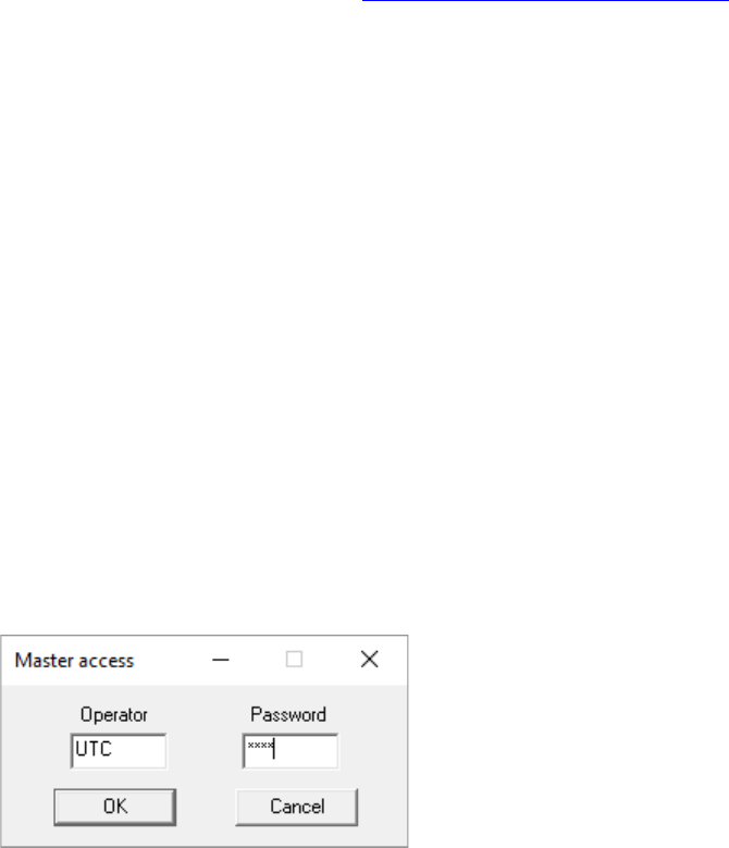
64 Installation and Programming Guide
DLX900 Software
DLX900 is a tool for programming Aritech Reliance XR systems. This software is installed on
a PC with Microsoft Windows 7, 8, or 10. It features a graphical interface, allowing installers
and Central Monitoring Stations to program and manage complex sites.
Customer details and all panel programming are stored in a local database on the
computer. This allows companies to create standard templates for quicker programming of
customer panels.
Installing DLX900
Download the latest version from https://www.ARITECH.com/library
You will need administrator privileges to install DLX900.
Double click the installation file and select the correct region. This will affect the panels the
software will support.
Upgrading from DL900
DLX900 in Australia supports legacy NetworX panels.
If DL900 has been installed previously, DLX900 can automatically import and upgrade the
database. It is recommended you save a backup of your database and ensure you have a
copy of DL900 in case you need to revert.
Once DLX900 is installed, right click the icon, click “More”, and select “Run as
Administrator”
Login to DLX
Default username and password for DLX900 is UTC 1234.
Enter this twice (once for master access, once for operator access) to login.
You must change the password. To change the default accounts and passwords: click
Program – Setup – Add/change Operators. Click the user then “Set Password”.

Installation and Programming Guide 65
To enable or disable password prompt(s): click Program – Setup – Program Setup.

66 Installation and Programming Guide
Navigating the Main Window
1. Window Title – displays currently selected customer’s account number.
2. Menu Bar – Program contains settings for DLX900, View turns on/off Toolbar and
Status Bar, View also has shortcut to the customer list, Control Panel displays all
top-level programming menus for the currently selected customer’s control panel,
Devices displays all programmed expansion devices, Download displays connection
commands, Tools displays DLX900 database management tools and Diagnostics.
3. View Customer – add/edit/delete customers, select customer to view.
4. View Customer List – show all customers in current DLX900 database.
5. Call control panel – use PSTN modem to connect to control panel.
6. Connect TCP/IP – connect to control panel using TCP/IP.
7. Disconnect – end current session and disconnect from control panel.
8. Send all data – send all programming menus from DLX900 to control Panel.
9. Read all data – read all programming data from control panel into DLX900.
10. View Status – view control panel system status (armed state, alarms, and troubles).
11. Read All Event Log – retrieve all event history.
12. Read 10 Events – retrieve last 10 items from event history.
13. Devices Enrolled – drop-down menu with shortcuts to enrolled expander devices.
14. Control Panel Menu – shortcuts to control panel settings, available on selected
panels.

Installation and Programming Guide 67
15. DLX900 Status – shows a progress bar of read and send commands, Caps Lock, Scroll
Lock, Num Lock, and Online/Offline connection state to control panel.
Customer Window
Each customer must have a unique Account Number.
Selecting a Customer
DLX900 will load programming for the currently displayed customer in any menus
displayed. Select a customer by:
• Using the Up and down arrow buttons to navigate through your customers;
• Entering the customer’s detail in the name or contact phone field, then click Goto;
• Clicking the Account number Goto, then enter the account number; or
• Clicking View Customer List, then click the customer displayed.
Duplicating a customer
DLX900 allows easy duplication of customer programming for similar sites.
1. Select a customer with the programming to duplicate.
2. Click Duplicate Customer.
3. Enter a new Account Number.
4. Tick “Copy customer information” if you want the contact details and serial number
of the panel to also be copied. This is useful if you are testing new programming for
the same customer.
5. Click OK.
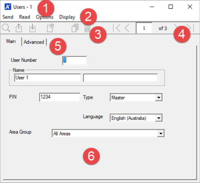
68 Installation and Programming Guide
Navigating the Menus
Each menu has a set of common elements:
1. Menu Name – displays the menu name and current customer’s account number.
2. Menu Bar – commands to Send data to the panel, read data from the panel, and
Options to restore factory defaults for this menu.
3. Tool Bar – Search for customers, send only this menu’s data to the panel, Read only
this menu’s data from the panel, Add a new record, Copy the current record, and
Delete the current record.
4. Navigation Buttons – jump to the first record, go back one record, enter a record
number, see the number of records for the current menu, go forward one record,
jump to the last record.
5. Sub-menu Tabs – these reflect the sub-menus in the Reference Guide.
6. Programming options – changes to these settings are saved immediately to the
database, to make them “active” perform a Send command.

Installation and Programming Guide 69
Control Panel Menu
This menu features all programming locations for the main panel. For supported models,
these menus also appear on the left side of the Main Menu.
Loading Control Panel Defaults
DLX900 can load factory default data for the currently selected customer panel:
1. Click Control Panel.
2. Click Default Control data from – Factory defaults.

70 Installation and Programming Guide
Devices Menu
The Devices Menu displays all expansion devices including keypads, input expanders,
output expanders, power supplies, touchscreen tablets, wireless devices, and keyfobs.
Each of these devices may have separate programming stored inside that device. This menu
allows you access to those programming locations.
Programming is retrieved from all enrolled devices when you perform a Read All.

Installation and Programming Guide 71
Device Info
Click Devices – Device Info to show all expansion devices:
The Device Info menu allows:
• Adding and removing of devices – click Remove Device, Auto Enroll, Manual Enroll,
or Add Device under the device category.
• Identification of devices – click Turn on / off Buss LED to flash an LED of the specific
device.
• Re-ordering of devices – drag and drop the device to re-number it, use the “Slot
condition after removing device” to determine if DLX900 should refresh all device
numbering or to reserve the device number for future use.
• Display of device information including firmware and serial number.
• Access programmed data – select the device and click Display Stored Data, this is
the same as accessing the device via the Devices Menu.
• Export of programming information for a specific device – select the device and click
Create file. DLX900 will create a special file. This file can be copied to a USBUP and
then inserted into a suitable device to program it without a computer.
• Export control panel information for use with USBUP – on the Control Info tab click
Create file to save current panel programming to a special file. This file can be

72 Installation and Programming Guide
copied to a USBUP and then inserted into a Aritech Reliance XR system to program it
without a computer.
Download Menu
This menu allows you to:
• Initiate a connection to the panel.
• Disconnect from a panel.
• Read all programming, including all connected expansion devices and backup copies
where available.
• Send all programming to the panel.
• Read the event log.
• Initiate a callback session before download, where this feature is enabled on the
panel.
• Write programming to a NX-586 / NX-588. This allows on-site programming of
selected panels without the need for a computer.
• Read programming from a NX-586 / NX-588. This allows retrieval of panel
programming from selected panels on-site without the need for a computer.
• Enable auto-answer for callback.
Reading Data
All programming located inside a customer panel can be retrieved and stored in the DLX900
database for further editing or backup purposes.
Reading All Data
To retrieve the contents of all control panel menus and store it in DLX900:
1. Select the customer you want to connect to.
Installation and Programming Guide 73
2. Connect to the panel.
3. Click the Read All button on the toolbar. Alternatively, from any menu click Read –
Read Control to only retrieve panel programming without data stored inside
expansion devices.
4. Wait for the progress bar on the bottom right to complete. DLX900 will retrieve data
from multiple menus, each will have its own progress bar.
5. Disconnect from the panel.
6. All data is now stored in your local database. Any changes made in DLX900 will not
be reflected in the customer panel. To make changes “live”, follow the instructions
on Sending All Data.
Reading Data from a Selected Menu
Programming from a single menu can be retrieved from the control panel into DLX900:
1. Select a customer to connect to.
2. Connect to the panel.
3. Open the menu you wish to read.
4. Click Read – Read Menu.
5. Data from all tabs in the current menu will be read into DLX900. Wait for the
progress bar on the bottom right to complete.
6. Disconnect from the panel.
Sending Data
Once programming has been created in DLX900, it must be sent to the panel using a “Send”
command.
Sending All Data
To send the contents of all DLX900 menus to the control panel:
1. Select the customer you want to connect to.
2. Make all changes required to customer programming.
3. Connect to the panel.
4. Click the Send All button on the toolbar. Alternatively, from any menu click Send –
Send Control.
5. Wait for the progress bar on the bottom right to complete. DLX900 will send data to
multiple locations in the panel, each will have its own progress bar.
6. Disconnect from the panel.
7. All panel programming has been copied to the panel.

74 Installation and Programming Guide
Sending Data from a Selected Menu
Programming from a single menu can be sent from DLX900 to the control panel:
1. Select the customer you want to connect to.
2. Connect to the panel.
3. Open the menu you wish to send.
4. Click the Send – Send Menu.
5. Data from all tabs in the current menu will be sent to the panel. Wait for the
progress bar on the bottom right to complete.
6. Disconnect from the panel.
Tools Menu
This menu provides database management features to maintain DLX900. This includes:
• Compact Database – The database may grow in size over time with adding and
removing of customers. Click this option to clean the database and make it smaller.
• Repair Database – DLX900 will check the database for any errors and repair them
where possible.
• Backup Database – The database should be regularly backed up and copied off the
computer to a secure location. DLX900 will regularly request to perform a backup of
the database when you exit the program. To change the frequency of the backup
request, click Program – Setup – Program Setup – Backup Schedule.
• Restore Database – The database can be restored to a new computer if required.
• Import Customers – Specific customers can be recovered from an existing database
backup file. This will read all customers or a specific customer (account number) into
the current database.
• Export Customers – Specific customers can be saved to a new database.
• Diagnostics – Display real-time communication data between the panel and DLX900.

Installation and Programming Guide 75
Programming with DLX900
This section of the manual will describe the steps needed to program each feature using
the DLX900 software.
Selected screen shots of the Aritech Reliance XR Web Server are also included for your
reference. Similar screens appear on the UltraSync+ app.
Programming Instructions for System Options
Goal
Program System Options including time and date, tamper, siren, timers, and service
settings.
Pre-conditions
Time and date are automatically updated using a internet time server by default, this
setting is enabled under Communicator – IP Config.
If you want to allow Aritech Reliance XR to send diagnostic emails, then check email is set
up correctly under Communicator – Email and Aritech Reliance XR is connected to a
network.
Note: Ensure you set the correct time zone here.
Programming Sequence
Instructions
1. Open System
System
- System Clock
- General Options
- System Timers
- Siren Options
- Test Options

76 Installation and Programming Guide
2. Select the right Time Zone using the Hours and minutes offset
3. If you wish to update the time and date
4. Go to System and Siren Options
5. Select the settings you want to enable
6. Go to Timers

Installation and Programming Guide 77
7. Enter the settings for global timers. Note Entry/Exit times are not here, go to Areas-
Area Timers.
8. Go to Maintenance and Test
9. Enter a Diagnostic email interval. This is the number of days to wait before sending an
email at the specified time. This verifies email communication is working.

78 Installation and Programming Guide
Web Page

Installation and Programming Guide 79
Programming Instructions for Permissions
Goal
Create a list of permissions that will restrict users, keypads, and devices to specific parts of
the system.
Pre-conditions
Have programmed or customized Channel Groups, Area Groups, Menus, and Action
Groups. Alternatively, you can use the preset groups.
Programming Sequence
12. Area Groups
11. Permissions
- Control Groups
- Permission Options
- User Timers
13. Menus
12. Area Groups
18. Channel Groups
19. Action Groups
18. Channel Groups
User
- User Name
- PIN
- User Type / Custom
11. Permissions
7. Schedules
10. Devices
11. Permissions
7. Schedules
13. Menus
19. Action Groups

80 Installation and Programming Guide
Instructions
1. Open Permissions
2. Select the permission number you want to modify
3. Enter a functional name for the permission
4. Select the Groups for each item which will give access to the items selected inside the
group. For example, if this permission is assigned to a user, then that user will have
access to Arm each of the Areas that are selected inside the Area Group and no others.
5. Click the Options/Timers tab

Installation and Programming Guide 81
6. Select the user options that you want to apply to this permission. Descriptions of each
item are available in the Aritech Reliance XR Reference Guide.
Next
• Program Users or Devices
Programming Instructions for Menus
Goal
Create a list of menus that a user or device has access to on the Aritech Reliance XR system.
Pre-conditions
None.
Notes
The menus that will be available are the ones that the device has permission to display AND
the ones that a user has access to, at the specified time and date which is controlled by
Schedules.
Users have up to 4 levels of access and devices have up to 2. This allows very sophisticated
and fine-grained control of access.
64 custom menus can be created. The preset ones will help you create a system quickly
without needing to modify these.

82 Installation and Programming Guide
Programming Sequence
Instructions
1. Open Menus
2. Select the Menu number
3. Enter a descriptive name
4. Tick each item that you want a user / device to have access to.
Permissions
- Control Groups
- Permission Options
- User Timers
13. Menus
12. Area Groups
18. Channel Groups
19. Action Groups
10. Devices
11. Permissions
7. Schedules
13. Menus
User
- User Name
- PIN
- User Type / Custom
11. Permissions
7. Schedules

Installation and Programming Guide 83
Next
• Program Permissions
• Assign the Permission to a User or a Device
Programming Instructions for Holidays
Goal
Create a list of holidays to provide or prevent access to the Aritech Reliance XR system on
the specific dates.
Pre-conditions
None.
Notes
Ticking Holidays in a Schedule for a permission PREVENTS access.
Holiday schedules may impact automation features such as Actions if they are in use. For
example, you may not want an Action to play on a holiday, so take care in programming the
associated Schedule and permissions.
Programming Sequence
Instructions
1. Open Holidays
14. Holidays
7. Schedules
14. Holidays

84 Installation and Programming Guide
2. Select one of the 4 Holidays available
3. Enter a name for the Holidays
4. Enter the start and end date for each holiday you have
Next
• Program Schedules
Example
An office is not staffed during a public holiday and you want to prevent access to the
building to staff on this date.
The public holidays in NSW, Australia for 2019 are:
New Year's Day
1 January
Australia Day
26 January
#Additional Day
28 January
Good Friday
19 April
Day following Good Friday
20 April
Office Worker
User Permission 1 – All Areas
Office Schedule 1 – 8am-8pm M-F,
Holidays 1 (ticked)

Installation and Programming Guide 85
Easter Sunday
21 April
Easter Monday
22 April
Anzac Day
25 April
Queen's Birthday
10 June
Labour Day
7 October
Christmas Day
25 December
Boxing Day
26 December
Open Holidays and program the date ranges.
Next, go to Schedules and tick “Holidays 1”:

86 Installation and Programming Guide
Then assign that schedule to the User:

Installation and Programming Guide 87
Programming Instructions for Users
Goal
Add/Edit/Remove users from your Aritech Reliance XR system.
Pre-conditions
• Have programmed or customized Permissions. Alternatively, you can use the defaults.
• Have programmed or customized Schedules. Alternatively, you can use the defaults.
Notes
PIN codes must be unique across the system, no two users can share the same PIN code.
PIN codes must be 4 to 8 digits in length.
Username must be assigned to give that user access to UltraSync+ app or Aritech Reliance
XR Web Server. A user with no first name will be unable to gain remote access.
The default installer account is User 256 with username installer and PIN 9713, with Master
Engineer user type. These details are used to Log in to the Web Server web pages and
UltraSync+ app.
The default master account is “User 1” and PIN 1234
The default standard account is “User 2” and PIN 5678
Programming Sequence
Instructions
1. Open Users
11. Permissions
a) Groups
b) Options/Timers
13. Menus
12. Area Groups
18. Channel Groups
19. Action Groups
1. User
a) Main
b) Advanced
11. Permissions
7. Schedules
7. Schedules
14. Holidays

88 Installation and Programming Guide
2. Select the User number you want to modify with the Left and Right arrow keys on the
top right. You can also Search, Add, Copy, and Delete a user by clicking the
corresponding button on the toolbar.
3. Enter a first name and/or last name for the user. It is case sensitive and provides the
username to log in from the UltraSync+ app.
4. Enter a new PIN code for the user. It must be unique and 4-8 digits long.
5. Select the user type that you want to apply to this user. Descriptions of each type are
available in the Aritech Reliance XR Reference Guide.
6. The Status option determines if that user can interact with the system, or if their access
has expired.
7. Click the Advanced tab.

Installation and Programming Guide 89
8. You can set the start/end date and time for when this user will have access to the
system. This can be used to provide temporary user access. If Active is selected on the
previous tab, then the end date and time on this screen will be set to maximum.
9. You can program up to 4 levels of access for each user. Permission 1 is applied when
Schedule 1 is true.
The combination of one Permission and one Schedule is called a “Permission Profile”
(left drop-down menu). Permission Profile 1 is the highest level and will override
Permission Profile 2 when Schedule 1 is active. Refer to Aritech Reliance XR Reference
Guide for more details.
To enable Permission Profiles the user type must be first set to Custom on the Main tab.

90 Installation and Programming Guide
Web Page
Programming Instructions for Zones
Goal
Program zones and add them to Areas.
Pre-conditions
None.
Notes
Use defaults for Zone Types and Zone Options to quickly set up your system.
Zones can have one or two profiles. The first profile will be active during the selected
schedule, it takes priority over the second profile/schedule. The second profile will be
active during the selected schedule if the first profile is not active.
If no schedule is set (or is currently active) in either the first or second zone profile, then
the zone will be disabled.

Installation and Programming Guide 91
See the next section for programming custom zones.
Programming Sequence
Instructions
1. Go to Zones.
2. Select a zone number you want to program.
3. Enter a name for the zone.
4. Select a zone type preset.
5. Select a zone option preset.
6. Select an Area Group for the zone. If you want a zone to be in its own Area, then select
an Area Group with only one Area. To create a zone in a common Area, select an Area
Group with multiple Areas. Alternatively come back to this step later.
15. Zone Types
- Area Armed
- Area Disarmed
16. Zone Options
15. Zone Type
16. Zone Options
12. Area Group
7. Schedule
1. User
Zones
- First Zone Profile
- Second Zone Profile
7. Schedules
14. Holidays
4. Areas
- Entry-Exit Times
- Area Options
- Area Timers
- Area Reporting
12. Area Groups
7. Schedule
18. Channel Groups

92 Installation and Programming Guide
7. For a standard installation set the schedule to a preset which is 24 hours every day,
holidays should NOT be ticked in this schedule. This will enable the first zone profile.
If you want the zone settings to change based on a schedule, then select the first
schedule here.
8. If you are setting up a keyswitch zone, then the user number field controls which user
profile will be used to arm/disarm. The keyswitch zone will report as default User 99.
9. If you are programming a second zone profile, then go to that now and repeat steps 4-
7.
Web Page
Next
• Zones are assigned to one or more Areas using Area Groups. If necessary, program
Areas and Area Groups, then assign an Area Group to each zone (step 6).

Installation and Programming Guide 93
Programming Instructions for Custom Zones
Goal
Program zones with advanced customization, including setting zone behavior to follow a
schedule or armed/disarmed state.
Pre-conditions
Program the schedule you want the zone to follow if needed. Alternatively use the defaults.
Programming Sequence
15. Zone Types
- Area Armed
- Area Disarmed
16. Zone Options
- Zone Options
- Zone Reporting
- Zone Reporting Event
15. Zone Type
16. Zone Options
12. Area Group
7. Schedule
1. User
3. Zones
- First Zone Profile
- Second Zone Profile
7. Schedules
14. Holidays
4. Areas
- Entry-Exit Times
- Area Options
- Area Timers
- Area Reporting
12. Area Groups
7. Schedule
18. Channel Groups

94 Installation and Programming Guide
Instructions
1. Go to Zone Type.
2. Go to Zone Options.

Installation and Programming Guide 95
3. Select the options you want, the SIA/CID event code can be customized. See the Aritech
Reliance XR Reference Guide for a table of codes.
4. Go to Zones.
5. Select a zone number you want to program.
6. Enter a name for the zone.
7. Select the zone type profile you just created.
8. Select the zone options profile you just created.
9. Select an Area Group for the zone. If you want a zone to be in its own Area then select
an Area Group with only one Area. To create a zone in a common Area, select an Area
Group with multiple Areas. Alternatively come back to this step later.
10. For a standard installation set the schedule to a preset which is 24 hours every day,
holidays should NOT be ticked. For example, “Always On”. This will enable the first zone
profile.
If you want the zone settings to change based on a schedule, then select the first
schedule here.
If no schedule is set in either the first or second zone profile then the zone will be
disabled.
11. If you are setting up a keyswitch zone, then the user number field controls which user
profile will be used to arm/disarm. The keyswitch zone will report as default User 99.
12. If you are programming a second zone profile, then go to that now and repeat steps 4-
7.

96 Installation and Programming Guide
Next
• Zones are assigned to one or more Areas using Area Groups. If necessary program Areas
and Area Groups, then assign an Area Group to each zone (step 8).
Programming Instructions for Areas
Goal
Program Areas, Entry/Exit Times, Reporting Options, and Area Groups.
Pre-conditions
Programmed Communicator, Channels, and Channel Groups.

Installation and Programming Guide 97
Programming Sequence
Instructions
1. Go to Areas.
2. Select an Area Number.
3. Enter a descriptive name.
4. Select the Options you want to enable for this Area. Area 2 and above have “Use Area 1
Options” ticked to allow faster programming of your system. Untick this box if you want
to customize options for Area 2 and above.
18. Channel Groups
6. Communicator
- General Options
- IP Configuration
- Cellular Configuration
- Username
- Password
- APN
- Remote Access
- System Event
Reporting
5. Channels
18. Channel Groups
6. Communicator
17. Event Lists
4. Areas
- Entry-Exit Times
- Area Options
- Area Timers
- Area Reporting
12. Area Groups
7. Schedule
18. Channel Groups

98 Installation and Programming Guide
5. For advanced programming you can assign a Schedule and an Area Time Disarm
function to occur according to the schedule. Refer to the Aritech Reliance XR Reference
Guide for more details.
6. Go to Area Timers.
7. Enter the timers that apply to this Area.
8. Go to Area Reporting.
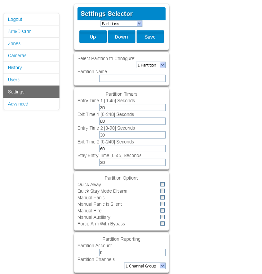
Installation and Programming Guide 99
9. Assign the Area an account number and the Channel Group you want this Area to report
to. See Programming Instructions for Zone Reporting for more details on how this
works.
Next
• Customize Area Groups if needed.
Webpage
Programming Instructions for Schedules
Goal
Create a schedule to provide or prevent access to the Aritech Reliance XR system on the
specific dates and times.
Pre-conditions
Holidays have been programmed if needed.

100 Installation and Programming Guide
Notes
Ticking Holidays in a Schedule PREVENTS access on the holiday dates.
Aritech Reliance XR automatically handles schedules that span midnight (e.g. bakers’
hours), do not tick the following day of the AM hours. (See Reference Guide for more
details.)
Programming Sequence
Instructions
1. Go to Menu 7 – Schedules.
2. Enter a name for the Schedule.
3. Select the first Start and End time.
4. Select the days you want this start and end time to apply to.
18. Channel Groups
14. Holidays
7. Schedules
14. Holidays
Installation and Programming Guide 101
5. If you are using the DLX900 software you will be able to see 4 sets of times and days,
click the drop-down in the middle to access more. Each schedule can have up to 16 sets
of times and days.
If you are using an NXX-1820- , press the Up and Down buttons to access the 16 sets of
times and days.
6. To allow an Action to control when this Schedule is active/inactive, select the Follow
Action Number.
7. Now the schedule is ready to be assigned to a User or used by another part of the
system.

102 Installation and Programming Guide
Webpage

Installation and Programming Guide 103
Example
For example, you could create a 24/7 schedule and then have this schedule follow an
action. Next assign a keypad permission this schedule. Now based on what the action does,
we can conditionally enable or disable a keypad. This provides a high level of flexibility and
multiple sets of rules using actions can be set up like this.
Programming Instructions for Arm-Disarm
Goal
Automatically arm and disarm your Aritech Reliance XR system.
Pre-conditions
Areas have been programmed.
Notes
After Arm-Disarm is programmed, a user must arm the system to initiate the function.
The Arm-Disarm will function as if it is the user you select. You will need to program valid
user permissions including Area Groups, User Schedule, Profile levels, and active date and
time.
Creating a new user only for the purpose of Arm-Disarm will make it easier to maintain.
Use defaults for Schedules, Area Groups and Permissions for faster programming.
Aritech Reliance XR will sound a warning prior to the Arm-Disarm from arming an Area. This
is set in Areas – Area Timers – Area Type Delay.
If a user with Area Type Override option disarms an Area with Arm-Disarm, then the Arm-
Disarm will no longer function on that Area. To re-enable Arm-Disarm that Area must be
manually armed.
Programming Sequence
4. Areas
- Entry-Exit Times
- Area Options
- Area Timers
- Area Reporting
12. Area Groups
7. Schedule
18. Channel Groups
7. Schedules
14. Holidays
7. Schedule
18. Channel Groups
9. Arm/Disarm
11. Permissions
- Control Groups
- Permission Options
- User Timers
13. Menus
12. Area Groups
18. Channel Groups
19. Action Groups
1. User
- User Name
- PIN
- User Type / Custom
11. Permissions
7. Schedules

104 Installation and Programming Guide
Instructions
1. Create an Area Group and select the Areas you want to be Armed according to the
schedule you will create later.
2. Create an Area Group and select the Areas you want to be Disarmed according to
schedule. This can be the same or different as the Area Group you selected above.
3. Create a Permission and select the corresponding Area Group for Arm and Disarm.
4. Open Users and create a new user. Suggested you provide a descriptive name such as
“Auto Arm User” to make troubleshooting in the future easy.

Installation and Programming Guide 105
5. Go to the Advanced tab.
6. Select the Permission you created above. If you want a simple Arm-Disarm then leave
the Schedule here as Always On. The Schedule selected here is only for the User. It
determines when the User is allowed to perform an Arm-Disarm, not when the Arm-
Disarm will occur.

106 Installation and Programming Guide
7. Create a Schedule for when you want the Arm-Disarm to occur.
8. Open Arm-Disarm.
9. Select the Arm-Disarm number.
10. Enter a descriptive name for this Arm-Disarm.
11. Enter the User number you created above.
12. Select the Schedule for when you want to automatically Arm-Disarm the system.
13. Test the Arm-Disarm to ensure it is working as you want.

Installation and Programming Guide 107
Example
An office with 3 Areas wants to automatically be disarmed during office hours, and armed
out of office hours.
We create Schedule 4 Mon-Fri 9am-5pm. Then User 55 with permission to arm and disarm
Area 1, 2, and 3 at any time or day.
Then each weekday at 9am the system will disarm Areas 1, 2, and 3 as if it were user 55 and
report those disarm events (openings) to the communication channels specified.
At 5pm each weekday the system would arm Areas 1, 2, and 3 as if it were user 55 and
report those arm events (closings) to the communication channels specified.
Programming Instructions for Communicator
Goal
Configure each communication path for delivering event messages.
Pre-conditions
None.
Arm-Disarm Number 1 - Arm-Disarm Example
Schedule 4 – Office Hours
Mon – Fri
9 AM – 5 PM
User 55 – Arm-Disarm User
Permission 99 – Full Access
Schedule 1 – Full Access
7 days, 24 hours
Arm Area Group 1
1, 2, 3
Disarm Area Group 1
1, 2, 3
See Schedule to
program
See Permissions to
program
See Users to
program
See Schedule to
program

108 Installation and Programming Guide
Programming Sequence
Instructions
1. Open Communicator.
2. Select reporting options.
3. Select when you want Aritech Reliance XR to perform an automatic communication
test.
4. Click IP Config.
6. Communicator
- General Options
- IP Configuration
- Cellular Configuration
- Username
- Password
- APN
- Remote Access
- System Event Reporting
18. Channel Groups

Installation and Programming Guide 109
5. Edit IP settings for the Aritech Reliance XR system, if DHCP is enabled on the Aritech
Reliance XR and a DHCP server is available, then this screen will automatically be filled
in.
• Enable Clock Updates – will keep the time and date correct using the provided
Internet Time Server, no manual adjustment will be needed when daylight savings
occurs provided the time zone is set correctly in System.
• Monitor LAN – this will monitor the physical LAN connection and report
communication fail if the cable is disrupted.
6. Click Radio and enter settings if required, this will depend on the SIM card and operator
you are using.

110 Installation and Programming Guide
7. Click Remote Access
8. Edit Remote Access settings for the Aritech Reliance XR system.
• Download Access Code – gives access to DLX900 to access the Aritech Reliance XR
panel programming.
9. Click System Event Reporting.
10. Select the channel group to send system events (e.g. low battery)
Next
• Perform tests on each of the communication paths to verify they are functioning
correctly.
• Program Channels.
• Program Channel Groups.
• Verify Number of Attempts, next channels (back-up channels), and multi-path reporting
function correctly.

Installation and Programming Guide 111
Programming Instructions for UltraSync
Pre-conditions
1. At least one user has been given a username and PIN code (see "Programming
Instructions for Users" on page 87).
2. Aritech Reliance XR is connected to internet and has been allocated an IP address (see
"Programming Instructions for Communicator" on page 107, IP Config).
Notes:
UltraSync provides a secure VPN connection to your Aritech Reliance XR system over the
internet. You will need to provide your Aritech Reliance XR serial number, Web Access
Passcode, and a valid Username and PIN code that exists in your Aritech Reliance XR
system. These codes provide multiple levels of security for the connection.
The Web Access Passcode is needed for:
• web console over the internet via a secure VPN
• UltraSync+ app
• DLX900 software connecting over IP, in addition to Download Access Code
The Web Access Passcode is NOT needed for:
• email services
• web console over a local LAN connection
Once UltraSync is set up, you may connect to your Aritech Reliance XR system using the
UltraSync+ app on your smartphone or tablet. This may require a separate account and
downloading additional software. See further instructions in the User Manual.
Instructions
1. Go to Menu 6 – Communicator, 3 - IP Config.

112 Installation and Programming Guide
2. Under sub-menu 12 - IP Options, tick the box “Enable UltraSync”.
3. Go to Menu 22 - UltraSync.
4. Enter a new 8-digit Web Access Passcode. All zeros will disable UltraSync remote access.
5. Enter the required details into your device/software. This includes the Aritech Reliance
XR serial number, Web Access Passcode, and a valid Username and PIN code. The
Aritech Reliance XR serial number can be found in the Device Info menu.
6. Verify the UltraSync service is working by using your device/software to connect your
Aritech Reliance XR system.
Troubleshooting
• Check the Web Access Passcode is correct. It cannot be 00000000.
• Check there is a valid user, and they have a First name, this will be the login name.
• Check the serial number is correct. It is printed on the Aritech Reliance XR module.
• Check that the user permissions are currently valid.
• See Troubleshooting Section in the Appendix for more information.
Programming Instructions for Event Lists
Goal
Create segmented lists of events so Channels can selectively deliver event messages.
Pre-conditions
None.

Installation and Programming Guide 113
Notes
If an event message is enabled in an Event List, then the Channel will attempt to deliver it. If
an event message is not enabled on the Event List, the Channel will not attempt delivery
even if the message has been sent to it.
Event List set up for push notifications is automatically performed by the UltraSync+ app
when required. The panel will assign the next available channel and matching event list
number. No configuration via the web pages or DLX900 is required.
Programming Sequence
Instructions
1. Open Event Lists.
2. Enter a name for the list.
3. Check the events you want to include in the list.
17. Event Lists
16
5. Channels
16
6. Communicator
17. Event Lists

114 Installation and Programming Guide
Example
In this example we have created two lists: Critical and Informational. This allows us to
selectively deliver event messages to different destinations.
We open up Event Lists and enter the name “Critical”. We tick Alarms, Alarm Restores,
Bypass and Bypass Restore, and AC Fail Reporting.
Then we click to Event List 2 and enter the name “Informational”. Tick Opening and Closing,
and Autotest Report.
Programming Instructions for Channels
Goal
Set up communication paths and destinations for delivering event messages.
Pre-conditions
1. Communicator must be programmed (see "Programming Instructions for
Communicator" on page 107).
2. Event Lists must be programmed (see "Programming Instructions for Event Lists" on
page 112).
3. If reporting to a control room, the panel must be provisioned in the UltraSync Portal.
The provisioning process sets the primary and secondary paths (IP/cellular), local path
fail detection, and server-based path monitoring settings.
Notes:
Area Account Number will take priority over Account Number entered here for Zone
events. If no Area Account Number is entered, then this number will be used instead.
Channel Group 1
Channel 1
Channel 4
Channel 6
Event List 1
Critical
Event
Menu 6.11.1.1 or 4
Channel Group 1
System / Area
Channel 4
Control Room 2
Event List = 1
Channel 6
Email
Event List = 2
Channel 1
Control Room 1
Event List = 1
Menu 18 – Channel Groups
Event sent to
Channel Group
Channel Group sends event
to every Channel it contains
Menu 5 – Channels
Each channel checks to see
if the event is on its Event
List, if yes it will attempt to
send, if not then it stops.
Menu 17 – Event Lists
Event List 2
Informational
Open & Closes
Autotest
Alarms
Bypass & Restore
AC Fail

Installation and Programming Guide 115
Next Channel must be a higher value than the current Channel Number. Circular loops are
not permitted.
Take note of the Sequence Attempts under Communicator – System Event Reporting
(6.11.2). This is the number of times Aritech Reliance XR will attempt the sequence of
Channels you set up in this section.
Channel set up for push notifications is automatically performed by the UltraSync+ app
when required. The panel will assign the next available channel and matching event list
number. No configuration via the web pages or DLX900 is required.
Programming Sequence
Instructions
1. Go to Channels.
5. Channels
18. Channel Groups
18. Channel Groups
6. Communicator
- General Options
- IP Configuration
- Cellular Configuration
- Username
- Password
- APN
- Remote Access
- System Event Reporting
17. Event Lists
6. Communicator
17. Event Lists

116 Installation and Programming Guide
2. Enter an Account Number up to 8 digits, hex values are accepted.
3. Select the Format of the communication channel, this will automatically use the settings
programmed for that Format in the Communicator menu.
If reporting to a control room via UltraSync, this must be set to “UltraSync”.
4. Select the reporting device, by default Device 1 is the Aritech Reliance XR panel.
5. Enter the destination email address or IP address depending on which Format you
selected.
If reporting to a control room via UltraSync, this can be left blank for SIA or CID event
messages.
6. Select what events you want to be sent via this Channel by selecting the appropriate
Event List. Events that arrive at this channel will be checked that they on this Event List,
if they are, then will be routed through this Channel. Events that arrive at this Channel
which are not on this list will be blocked.
If the currently selected Channel is used for push notifications to UltraSync+ app, the
Event List number must be the same as the Channel number.
7. Enter the number of Attempts that you want Aritech Reliance XR to try sending the
event message on this Channel before switching to the Next Channel.
8. Select the Next Channel Number to use if the event message fails to be sent on this
Channel.
Each Channel can have one Next Channel as a backup. This allows you to chain up to 15
backup paths should the primary one fail. Enter Next Channel as 0 to end the chain of
channels.
9. You have now finished programming one channel. If you entered a Next Channel, then
go to that Channel number and program that now.

Installation and Programming Guide 117
10. Once you have programmed each channel and backup channel(s) you have completed
this section. Check or edit Sequence Attempts under Communicator – System Event
Reporting (6.11.2).
11. Go to Channel Groups. Here you will group channels together so selected event
messages will be sent to multiple destinations at the same time. Another way to think
of Channel Groups is “multi-path reporting”. Note this is in addition to WiFi/Ethernet
and Cellular backup where equipped and provisioned by UltraSync Portal.
12. Select each channel you want to be part of a group.
Messages sent to a Channel Group will be checked against each Channel’s Event List. If
it is on the list then Aritech Reliance XR will attempt to send it. If not, then Aritech
Reliance XR will not send it, even if the Channel is in the same group.
13. Done. Your Channels are now set up and ready for use. When an event is generated by
the system or a zone it can now be sent to a Channel for reporting.
Example
In this example we have multi-path, prioritised/selective event reporting via three reporting
paths – one control room with backup, push notification to a smartphone, and an email
address. These are grouped into “Channel Group 1”.
All alarms are reported to Control Room 1 and push notification goes to UltraSync+ app
installed on User 1’s smartphone. Control room 1 has a backup receiver.
When a channel receives an alarm message, Aritech Reliance XR checks that the channel’s
Event List includes alarm messages and then attempts to deliver the message via that
channel.
When Channel 1/2/4 receives a low battery report, it is ignored because Event List 1 does
not include the “low battery” event.
Low priority alerts such as opening and closings, low batteries, and auto test reports, are
selected in Event List 2. Channel 6 handles Event List 2 and sends these events as an email
to a building manager. When Channel 6 receives the Zone 3 in Alarm event it takes no
action because Event List 2 does not include “Alarms”.

118 Installation and Programming Guide
Notice that Channel 2 is not selected in Channel Group 1. The Aritech Reliance XR will
deliver to Channel 2 only if Channel 1 cannot be reached. If Channel 2 were included in
Channel Group 1, then the control room may receive duplicate messages.
Next
• Program your Areas and Zones.
Programming Instructions for Zone Reporting
Goal
Direct event messages (e.g. alarm, bypass, tamper) from zones to specific destinations.
Pre-conditions
• The zone must have valid zone options programmed (see "Programming Instructions for
Zones" on page 90), by default you should not need to modify these.
• The zone must be allocated a valid Area Group (see "Programming Instructions for
Zones" on page 90).
Channel Group 1
Channel 1
Channel 4
Channel 6
Zone 3 in Alarm
Menu 17 – Event Lists
Alarms
Event List 1
Channel 4
UltraSync+ App
Format = Notifications
Destination = phone@u1
Event List = 4
Next Channel = 0
Channel 6
Email
Format = Email
Destination = alex@home.com
Event List = 2
Next Channel = 0
Channel 1
Control Room 1
Format = UltraSync
Event List = 1
Channel Attempts = 3
Next Channel = 2
Menu 18 – Channel Groups
Area sends account
number and event to
Channel Group
Channel Group sends
Event to every Channel it
contains
Menu 5 – Channels
Channel 2
Control Room 1
Format = Backup
Event List = 1
Channel Attempts = 3
Next Channel = 0
After failing Channel Attempts on the last back up channel,
Aritech Reliance XR will go back to the first Channel in the chain
Report Attempts = 2
Channel checks if the event is on its Event
List, if yes it will attempt to send, if not
then it stops
Opening & Closing
Low Battery
Autotest
Event List 2
If it does not succeed after Channel
Attempts, it will try sending on the next
Channel
Aritech Reliance XR attempts to
send event via email using the
UltraSync servers
Aritech Reliance XR attempts to
send event via push notification
to smartphone. Event list
number always matches
channel number.
Alarms
Event List 4
Event Lists filter
events from
passing through
the Channel

Installation and Programming Guide 119
• Channels and Channel Groups must be programmed (see "Programming Instructions for
Channels" on page 114).
Notes
Each zone may be allocated to multiple Areas through an Area Group.
Events will be sent to the lowest numbered Area in the Area Group.
A zone may have a Second Zone Profile, when this becomes active all events will be sent to
the Area Group programmed in the second profile.
Programming Sequence
Instructions
1. Open the lowest Area number for the Zone.
3. Zones
4. Areas
- Entry-Exit Times
- Area Options
- Area Timers
- Area Reporting
7. Schedule
18. Channel Groups
12. Area Groups

120 Installation and Programming Guide
2. Go to Area Reporting.
3. Enter an account number.
4. Select a valid Channel Group.
5. Done. All zones that are a part of that Area will now report to the selected Channels
within the Channel Group.
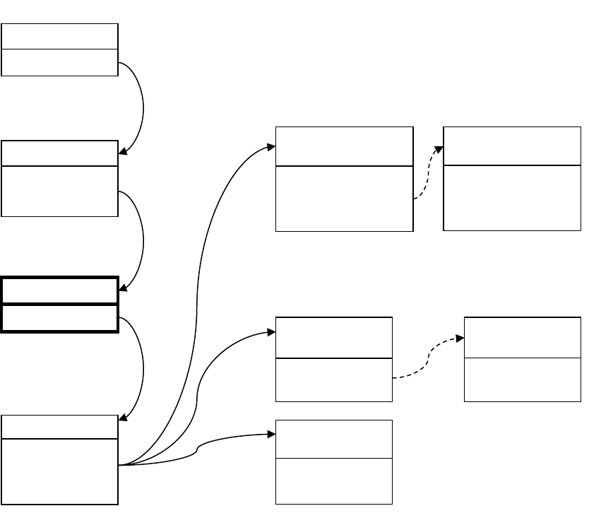
Installation and Programming Guide 121
Example
Next
• Program Users.
• Program advanced Schedules and Alternate Zone Profiles.
Programming Instructions for System Event Reporting
Pre-conditions
• Communicator must be programmed (see "Programming Instructions for
Communicator" on page 107).
• Event Lists must be programmed (see "Programming Instructions for Event Lists" on
page 112).
• Channels and Channel Groups must be programmed (see "Programming Instructions for
Channels" on page 114).
Notes
The system event will only be reported by a channel, if that Channel includes that event in
the associated Event List(s).
Channel Group 1
Channel 1
Channel 4
Channel 6
Zone 3 in Alarm
Area Group = 1
Area Group 1
Menu 12 – Area Groups
Area 1
Area 2
Menu 4 – Areas
Channel Group 1
Area 1
Event sent to lowest Area
Channel 4
Control Room 2
Event List = 1
Next Channel = 5
Channel 6
Email
Event List = 2
Next Channel = 0
Channel 1
Control Room 1
Event List = 1
Channel Attempts = 3
Next Channel = 2
Menu 18 – Channel Groups
Area sends event to
Channel Group
Channel Group sends Event
to every Channel it contains
Menu 5 – Channels
Channel 5
Control Room 2
Event List = 1
Next Channel = 0
Channel 2
Control Room 1
Event List = 1
Channel Attempts = 3
Next Channel = 0
Channel checks to see if the event is
on its Event List, if yes it will
attempt to send, if not then it stops
Menu 3 – Zones
If it does not succeed after Channel
Attempts, it will try sending on the
next Channel
Zone sends alarm to Area group

122 Installation and Programming Guide
Take note of the Sequence Attempts under Communicator – System Event
Reporting (6.11.2). This is the number of times Aritech Reliance XR will attempt the
sequence of Channels you set up in this section.
Programming Sequence
Instructions
1. Go to Communicator, System Event Reporting.
2. Select a Channel Group.
3. Done. The Aritech Reliance XR will now report system events to the Channels selected
in the Channel Group you just selected.
5. Channels
18. Channel Groups
6. Communicator
17. Event Lists
17. Event Lists
18. Channel Groups
6. Communicator
- General Options
- IP Configuration
- Cellular Configuration
- Username
- Password
- APN
- Remote Access
- System Event Reporting

Installation and Programming Guide 123
Example
Programming Instructions for Actions
Goal
Create an action to monitor up to four input events and drive one output event (action
result).
Pre-conditions
Program the input and output events you want the Action to monitor or control.
Notes
See Aritech Reliance XR Reference Guide for more details on Actions.
Write/Plan out on paper what you want to create to make it easier to set up Actions and
associated settings.
Channel Group 1
Channel 1
Channel 4
Channel 6
Event List 1
Critical
Alarms
Bypass & Restore
AC Fail
AC Fail
Menu 6.11.1.1
Channel Group 1
System Event
Reporting
Channel 4
Control Room 2
Event List = 1
Next Channel = 5
Channel 6
Email
Event List = 2
Next Channel = 0
Channel 1
Control Room 1
Event List = 1
Channel Attempts = 3
Next Channel = 2
Menu 18 – Channel Groups
System sends event to
Channel Group
Channel Group
sends event
to every Channel
it contains
Menu 5 – Channels
Channel 5
Control Room 2
Event List = 1
Next Channel = 0
Channel 2
Control Room 1
Event List = 1
Channel Attempts = 3
Next Channel = 0
After failing Channel Attempts on the last back up channel, Aritech
Reliance XR will go back to the first Channel in the chain.
Sequence Attempts = 2
Channels 1 and 4 will attempt to send the event as AC Fail is on the
corresponding Event List. Back up channels 2 and 5 will also attempt to send
the event if they are used.
Channel 6 will NOT send the event as Event List 2 does not include AC Fail
events.
Menu 17 – Event Lists
Event List 2
Informational
Open & Closes
Autotest
Event 1
Event 2
Event 3
Event 4
Action
State
and
or
=
Action
Result
and
or
and
or
+
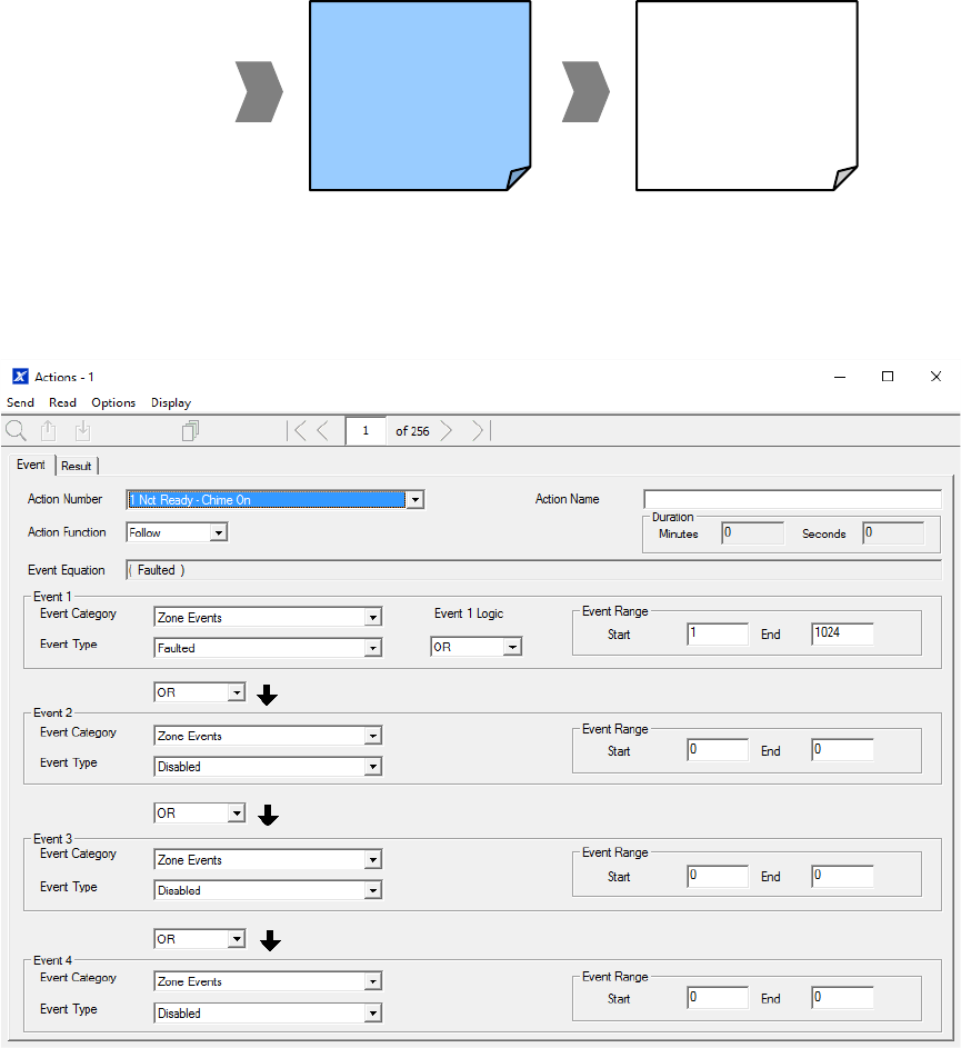
124 Installation and Programming Guide
Actions can be used without programming an Action Result. For example, outputs are
controlled by setting them to monitor an action, when the Action State is true the output
state will follow.
Programming Sequence
Instructions
1. Open Actions.
2. Select the Action Number you want to create.
3. Enter a descriptive name for this action.
4. Select the Action Function and the duration (optional) for the Action State.
For example, timed 5 seconds would cause the Action State to activate for 5 seconds
when all the conditions in the Event Equation are satisfied.
5. Select the Event 1 logic, this will be applied before Event 1.
For example, “Inverted OR” results in “NOT Event 1”.
6. Program the first event by using the Category and Type menus.
8. Actions
19. Action Groups
Events to be
monitored
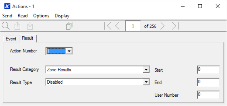
Installation and Programming Guide 125
7. Enter the Event Range for the selected Category.
For example, if you want to select Areas 1-4 then set the Event range Start=1 and
End=4.
8. Select Event 2 logic and repeat for the remaining events.
9. If you want to program an action result, click the Result tab.
10. Select the Category, Type, Start and End Range.
11. Test the Action by satisfying the Event Logic and checking the desired response.
Next
• Program the device you want to monitor the Action if needed.
• If you want to control an Output, go to that Output and program it to follow the Action.
• If you want a user or device to have access to the action, then program Action Groups
and Permissions.
Programming Instructions for Action Groups
Goal
Create a list of actions a user or device has access to.
Pre-conditions
Program the actions you want to use.
Notes
See Aritech Reliance XR Reference Guide for more details on Actions.
Action Groups can allow you to create a convenient menu for a user to trigger specific
Actions from a NXX-1820- .
Permissions control what actions a User or Device has access to.
Both the User AND Device need to have access to the desired Action for it to be displayed
on a NXX-1820- screen.

126 Installation and Programming Guide
Programming Sequence
Instructions
1. Open Action Groups.
2. Select an Action Group Number.
3. Enter a descriptive Name.
4. Select the Actions you want to include.
10. Devices
8. Actions
19. Action Groups
11. Permissions
7. Schedules
11. Permissions
- Control Groups
- Permission Options
- User Timers
13. Menus
12. Area Groups
18. Channel Groups
x. Action Groups
1. User
- User Name
- PIN
- User Type / Custom
11. Permissions
7. Schedules

Installation and Programming Guide 127
Next
• Assign Action Group to a Permission.
• Assign Permission to a User or Device.
Programming Instructions for Scenes
Goal
Create a scene that performs multiple functions when a certain condition is met.
Pre-conditions
The schedule you want the Scene to follow needs to be programmed.
Notes
User 99 will be reported for alarm system control events.
Programming Sequence
20. Scenes

128 Installation and Programming Guide
Instructions
1. Open Scenes.
2. Select Event Type and the Area.
3. Select the Schedule that will determine when this Scene is active.
4. Now program the sequence of actions that you want to happen.
Example
When Exit Delay 1 is running in the Office Area, set Camera 1 to start recording.
Programming Instructions for Outputs
Goal
Turn an output on or off according to an Action.
Pre-conditions
Program the Action and any associated components.
Event 1
Event 2
Event 3
Event 4
Action
State
and
or
=
Action
Result
and
or
and
or
+

Installation and Programming Guide 129
Notes
See Aritech Reliance XR Reference Guide for more details on Actions.
Write/Plan out on paper what you want to create. This makes it easier to set up Actions and
associated settings.
Actions can be used without programming an Action Result. For example, outputs on
Aritech Reliance XR are controlled by monitoring an Action State, no Action Result needs to
be programmed.
Programming Sequence
Instructions
1. Select the Device that has the physical outputs you want to control.
2. Select Outputs.
3. Select Action.
4. Select the Schedule.
Combining Actions with Schedules
Schedules can control when a user has access, when an automatic Arm-Disarm occurs,
when devices can be used, and more. Actions can turn Schedules on and off, making
Schedules conditional based on when certain events occur.
The outcome is that we can control Users, Permissions, Areas, Zones, Actions, Arm-Disarm,
Scenes, and Devices, based on various system conditions. This provides automation
features that allows the system to respond in real-time to changing conditions.
10. Devices
8. Actions
7. Schedules
14. Holidays
11. Permissions
7. Schedules
Action
Events
Schedule
ON/OFF
Action
State
Action
Result
controls
control
+
controls
User, Permissions, Area, Zones, Actions, Arm-
Disarm, Scenes, and Devices
130 Installation and Programming Guide
This functionality is achieved by going to that Schedule and selecting Follow Action
Number.
Take care when combining multiple schedules and actions as troubleshooting can get
confusing. Always check and test functionality a single step at a time. Users and Zones can
have multiple levels of permissions, be sure to check that each permission level is always
appropriate.
Example
When a certain user is in the building, we can prevent an automatic Arm-Disarm from
occurring.
First program an Action with the conditions you want and the Duration of the Action if
necessary.
Next program Arm-Disarm with a User and Schedule.
Then set the Schedule to Follow Action Number.
When the action events are met, then the Schedule will become active and will be able to
perform an Arm-Disarm at the appropriate time. If the conditions are not met, then the
Arm-Disarm will never occur.

Installation and Programming Guide 131
Arming and Disarming Your System
You may arm and disarm areas from a NXX-1820-keypad.
Only users with an authorized user code (Level 2 user) will be allowed to use the Aritech
Reliance XR alarm system. Users with no valid user code (Level 1 user) do not have access
as defined by EN 50131-3.
Lock Out On 3 Invalid Attempts
If an invalid PIN code is entered three times, the keypad will deny all log in attempts for 90
seconds. Attempts are counted from any method (e.g. keypad, app, or web page). You must
wait the full 90 seconds before trying again with the correct PIN. This is to prevent brute-
force attacks on guessing PIN codes.
Arm Your System In Away Mode
Enter a valid PIN code to unlock the screen.
Touch the Away or Away + button to arm your system in Away mode:
The icon will change to red when the alarm system is set in away mode.
If your system has multi-Area control enabled, the Away + button will be displayed.
A valid PIN code will need to be entered to determine what permissions they have; this
includes which Areas and at what time/day that user has access.
Arm Your System In Stay Mode
Enter a valid PIN code with Stay permissions to unlock the screen.
Touch the Stay or Stay + button to arm your system in Stay mode:
The icon will change to yellow when alarm system is set in Stay mode.
If your system has multi-Area control enabled, the Stay + button will be displayed.
A valid PIN code will need to be entered to determine what permissions they have, this
includes which Areas and at what time/day that user has access.
Arm Your System in Instant Stay Mode
Enter a valid PIN code with Stay permissions to unlock the screen.
To arm in Instant Stay mode, touch the Stay button two times until the icon is red and
displays “Instant”:
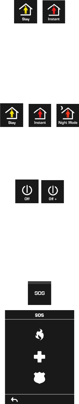
132 Installation and Programming Guide
This indicates the alarm system is set in Instant Stay Mode.
Arm Your System In Night Mode
Enter a valid PIN code with Stay permissions to unlock the screen.
To arm in Night Mode touch the Stay or Stay + button a total of three times until the icon is
red and displays “Night Mode”:
Touching the Night Mode button again will cycle the system back to Stay Mode.
Disarm One Or More Areas
Touch the Off or Off + button to disarm your system:
If your system has multi-Area control enabled, the Off + button will be displayed.
A valid PIN code will need to be entered to determine what permissions they have, this
includes which Areas and at what time/day that user has access.
Activate SOS Feature
Touch the SOS button to display the SOS feature:
On this screen touch and hold the appropriate button for 2 seconds to activate Manual Fire
Alarm, Manual Auxiliary Alarm, or Manual Panic Alarm. These buttons can be enabled and
disabled in the Area Options menu.

Installation and Programming Guide 133
Depending on how your system is programmed, the control room may receive the
corresponding event. Check with your control room to determine what action will be taken.
If silent alarm is enabled, then the keypad will not display any signs that the panic button
was pressed.
To cancel a SOS alarm – return to the home screen, touch the Status button and turn the
Area off.
Walk Test
1. Log in to panel web page.
2. Click Settings.
3. Click Walk Test.
4. Click Start.
5. Trigger each sensor by walking past PIRs, opening and closing reed switches,
pressing tamper buttons, etc. Siren will chirp multiple times for each zone triggered.
6. Click Stop.
7. Click History.
User Reporting
When enabled, quick arming/disarming from the keypad without a PIN code will report
user 98 to the Central Monitoring Station. SOS functions also report as user 98.
If the installer PIN is used to arm/disarm, user 256 is reported to the Central Monitoring
Station. On legacy NX keypads user 255 will appear in event history.
134 Installation and Programming Guide
Appendix 1: System Status Messages
Various messages may appear on the Status screen of Aritech Reliance XR Web Server and
UltraSync+ app.
System
• AC power fail – The security system has lost its electricity power. May take up to 5
min to clear once power restored.
• Low battery – The security system’s back up battery requires charging. May take up
to 5 min to clear once battery charged.
• Battery test fail – The security system’s back up battery requires changing. If after 48
hours this message does not clear, replace with a new battery. If the power fails, the
system will not be operational.
• Box tamper – The security system’s cabinet tamper input is open or either antenna is
not connected.
• Siren trouble – The security system’s external siren has a problem. Check the panel is
securely installed on the wall.
• Over current – The security system is drawing too much current. Disconnect some
hardwired inputs.
• Time and date loss − The security system time and date need resetting.
• Communication fault – The security system has detected a problem with the
communication channel. Check the internet connection, Ethernet cable, or cellular
reception is sufficient.
• Fire alarm – A fire alarm has been activated from the panel.
• Panic – A panic alarm has been activated from the panel.
• Auxiliary – An auxiliary alarm has been activated from the panel.
Area Number. Area Name
• Is on in the away mode – This Area is armed in the away mode.
• Is on in the stay mode – This Area is armed in the stay mode.
• Is ready – This Area is secure and ready to be armed.
• Is not ready – This Area is NOT ready to be armed, a zone is not secure.
• All Areas are on in the away mode – All Areas in this multi area system are armed in
the away mode.
• All Areas are on in the stay mode – All Areas in this multi area system are armed in
the stay mode.
• All Areas are ready – All Areas in this multi area system are secure and ready to be
armed.
Zone Number. Zone Name
• In alarm – This zone has triggered a system alarm condition.
• Is bypassed – This zone is isolated (disabled) and will not activate an alarm.
Installation and Programming Guide 135
• Chime is set – This zone is part of the chime group.
• Is not secure – This zone is not closed.
• Fire alarm – This zone has triggered a fire alarm.
• Tamper – This zone has triggered a tamper alarm.
• Trouble fault – This zone has an open circuit.
• Loss of wireless supervision – This zone is a wireless device and has lost its
communication link with the control panel. Check the zone is within range of the
panel and has sufficient battery.
• Low battery – This zone is a wireless device and needs a battery replacement.
136 Installation and Programming Guide
Appendix 2: App and Web Error Messages
Various error messages may appear in the Aritech Reliance XR Web Server and UltraSync+
app.
Advanced/Settings Configuration Menus
• "You must select a Menu before you can scroll" – An attempt was made to scroll up
or down from the top-level menu.
• "Select a submenu from the list or select back to access the main menu" – An
attempt was made to scroll up or down from a submenu that has no additional
levels.
• "Defaulting requires 2 levels" – a Shortcut was entered without two levels.
Read Write errors and results
• "Write Access Denied" – Changes cannot be saved; check you have permission or
contact your installer.
• "Nothing displayed can be Saved" – No changes are possible on this screen.
• "Program Success!" – Changes have been saved.
• "Name Saved" – Changes have been saved.
Zones Page
• "No Zones Configured for Your Access" – Displayed on Zones page when there are
no zones available to view
Data Entry Errors
• "Data must only contain the following characters"
• "Date must be of the form YYYY–MM–DD."
• "Day must be from 1 to 31"
• "Data entry must only contain the numbers 0–9 and A–F"
• "Data entry must only contain the numbers 0–9"
• "Data must be a number from X to Y"
• "Improper Time Value"
• "must be 4 to 8 digits
• "You must enter a user Number between 1 and 1048575"
• "PIN digits must be between 0 and 9"
• "PIN Must be 4–8 digits from 0–9"
• "Data must not contain the following characters []"
Installation and Programming Guide 137
Appendix 3: Advanced Menu Tree
1. Users
2. System
1. System Clock
2. General Options
3. System Timers
4. Siren Options
5. Service and Test Options
6. Status
7. System Counts
8. Language
9. Automation Menu
3. Zones
1. Zone Number
2. Zone Name
3. First Zone Profile
1. Zone Type
2. Zone Options
3. Area Group
4. Schedule Number
5. User Number
4. Second Zone Profile
4. Areas
1. Area Number
2. Area Name
3. Area Entry-Exit Times
4. Area Options
5. Area Timers
6. Area Type Settings
7. Area Event Reporting
5. Channels
1. Channel Number
2. Channel Name
3. Account Number
4. Format
5. Device Number
6. Destination
7. Next Channel
8. Event List
9. Attempts
10. Language
6. Communicator
1. General Options
2. Auto Test
3. IP Configuration
1. IP Host Name
2. IP Address
3. Gateway
4. Subnet
5. Primary DNS
6. Secondary DNS
7. Ports
8. Time Server
9. IP Options
4. Cellular Configuration
1. SIM1 User Name
2. SIM1 Password
3. SIM1 APN
4. SIM2 User Name
5. SIM2 Password
6. SIM2 APN
5. Remote Access
1. Panel Device Number
2. Download Access Code
3. Callback Server
4. Download Options
6. System Event Reporting
1. System Channel
2. Attempts
7. Schedules
1. Schedule Number
2. Schedule Name
3. Follow Action Number
4. Times and Days
8. Actions
1. Action Number
2. Action Name
3. Function
4. Duration Minutes
5. Duration Seconds
6. Event 1
7. Event 2
8. Event 3
9. Event 4
10. Result
9. Arm-Disarm
1. Arm-Disarm Number
2. Name
3. User Number
4. Schedule Number
10. Devices
1. System Devices
1. Control
2. Keypad
3. Zone Exp
4. Output Exp
5. Power Supply
6. Reliance
2. ARITECH Transmitters
1. Transmitter Number
2. Serial Number
3. User
4. Module Input
5. Options
6. Follow Action Number 1
7. Signal Strength
8. Sensor Application
9. Follow Action Number
3. Tablet Keypads
1. Name
2. Serial Number
3. Area Group
4. Keypad Options
11. Permissions
1. Permission Number
2. Permission Name
3. Control Groups
4. Permission Options
5. User Timer Options
12. Area Groups
1. Area Group Number
2. Area Group Name
3. Area List
13. Menus
1. Menu Number
2. Menu Name
3. Menu Selections
14. Holidays
1. Holiday Number
2. Holiday Name
3. Date Range
15. Zone Types
1. Zone Type Number
2. Zone Type Name
3. Zone Type Armed
4. Zone Type Disarmed
16. Zone Options
1. Zone Options Number
2. Zone Options Name
3. Zone Options
4. Zone Reporting
5. Zone Contact Options
6. Zone Report Event
17. Event Lists
1. Event List Number
2. Event List Name
3. Event List
18. Channel Groups
1. Channel Group Number
2. Channel Group Name
3. Channel List
19. Action Groups
1. Action Group Number
2. Action Group Name
3. Action Group List
20. Scenes
1. Scene Number
2. Scene Name
3. Activate Schedule
4. Activate Event Type
5. Activate Zone
6. Scene Actions
21. Cameras
1. Camera Number
2. Camera Name
3. LAN IP Address
4. MAC Address
5. Panel to Camera Connection
6. When Doorbell Button is Pressed
7. When Motion is Detected
22. UltraSync
1. Web Access Passcode
2. Ethernet Server 1
3. Ethernet Server 2
4. Ethernet Server 3
5. Ethernet Server 4
6. Wireless Server 1
7. Wireless Server 2
8. Wireless Server 3
9. Wireless Server 4
138 Installation and Programming Guide
Appendix 4: Troubleshooting
Connecting to the site with UltraSync+ app
If you have trouble connecting to your system using the app, here is a checklist:
• Check the serial number, web access passcode, user name and PIN codes match
those in the Aritech Reliance XR.
• Web Access Passcode must not be 00000000.
• Web Access Passcode must be from 4 to 8 digits.
• User Name must be entered with a space between the first and last name and with
correct capitalization.
• Check the User Name does not have an extra space at the end.
• If connected by Wired LAN, check the cable is plugged in and that the connection is
working.
• Check Settings – Network – Enable UltraSync is ticked.
• Check that your mobile device has access to the internet (e.g. open a web browser).
• Power cycle connected equipment including Aritech Reliance XR and customer
supplied router(s).
Viewing Cameras in UltraSync+ app
Check:
• Cameras must be added using UltraSync+ app “Add New Device” menu. This process
will activate the camera once a secure password has been set.
Manually adding a camera using the camera web page and panel web page (Menu –
Settings – Cameras) is only possible AFTER the camera has been activated by the
app.
• Camera has a good connection to the router. This is influenced by distance, barriers
and walls, environmental conditions such as other routers and home appliances.
When using the Aritech Reliance XR Router the nominal range is 10-30m.
• There is only one panel is on the same network. Each panel will periodically scan the
network for cameras in the background and take ownership of all cameras found. If
there is more than one panel on the same network, the cameras will swap panels
and become unavailable when logging in to that panel.
Installation and Programming Guide 139
Viewing Cameras on Touchscreen
If 7” WiFi Secondary Touchscreens are installed, check:
• Panel arming/disarming is possible. This confirms if the touchscreen is enrolled
correctly with the panel and that the WiFi network is working.
• Cameras are accessible from the UltraSync+ app, the video preview and live stream
should work. This confirms the camera is set up correctly, has access to the internet,
and can be authenticated by the panel. For local only panels (no internet and no
app), this step can be skipped.
• All cameras have a secure password.
• All touchscreens have the same password entered into the MENU – Touchscreen –
Camera Username / Password.
• Reboot the WiFi router.
