
GREAT EIGHT
PRO PLUS
&
METRO COIN
BATTERY
BILL ACCEPTOR
POOL TABLE
SETUP
PROCEDURE
Valley-Dynamo 2890 112
th
Street Grand Prairie, TX 75050
(800) 248-2837 (972) 595-5300 fax (972) 595-5380
www.valley-dynamo.com
85020506 REV A2 02-01-07
TABLE OF CONTENTS
(I) Battery Information and Speed Pool Instructions Page 1
(II) Initial Startup Page 2
(III) Setup of Operating Values Page 2 & 3
(IV) Default Values Page 3
(V) Setup Parameter Notes Page 4 & 5
(VI) A full list of the parameters and their limits Page 5 & 6
(VII) Reading the Stored “Book-Keeping” Totals Page 7
(VIII) Replacing the Battery or using the “On Board Charger” Page 8
(IX) Removing Dollar Bill Acceptor Page 9
(X) Great 8 Chip replacement & Startup Page 10
(XI) Additional notes about the new program and “On Board” Charger Page 11
(XII) Schematic for Valley-Dynamo board (Figure 2 or 8) Page 12
(XIII) Motor Assembly Drawing Page 13
(XIV) Trouble Shooting Guide Page 14 – 16
(XV) Push Chute Diagrams Page 17
(XVI) Adjusting the clock speed Page 18
(XVII) Player Operating Instructions Page 19
(XVIII) Quick reference Program Worksheet Page 20 - 21

(I)
IMPORTANT BATTERY INFORMATION
NOTE: EVEN THOUGH THE “LEAD ACID” BATTERY IS CHARGED AT
THE FACTORY, IT IS RECOMMENDED TO CHARGE THE
BATTERY FOR 24 HOURS PRIOR TO STARTING THE TABLE.
DO NOT LET YOUR BATTERY DISCHARGE
COMPLETELY! DRAINING YOUR BATTERY
COMPLETELY WILL DEGRADE OR DESTROY THE
BATTERY.
We recommend recharging every 30 days.
DANGER: BOARD DAMAGE MAY OCCUR IF YOU TRANSPORT
TABLE WITH THE BATTERY INSTALLED. DISCONNECT AND STORE
BATTERY IN CASH BOX (Push Chute).
SPEED POOL INSTRUCTIONS
To START and STOP the SPEED POOL Timer
Press the TIME / RACK TIME
Button next to the Dollar RACK
Bill Acceptor
Or the START Button START
next to the Q-Ball Return
Page 1

(II)
VALLEY BATTERY BILL ACCEPTOR POOL TABLE SETUP PROCEDURE
(READ ENTIRE MANUAL FIRST BEFORE PERFORMING THE FOLLOWING)
Initial Startup IMPORTANT
NOTE: EVEN THOUGH THE “LEAD ACID” BATTERY IS CHARGED AT THE
FACTORY, IT IS RECOMMENDED TO CHARGE THE BATTERY FOR 24
HOURS PRIOR TO STARTING THE TABLE.
Open the Bill Acceptor Access Door (FIGURE 1).
Bill Acceptor Access Button
Access Door
FIGURE 1 FIGURE 2
Connect the two battery leads to the battery, making sure to connect the yellow wire to positive (+) & the
black wire to negative (-). Place the charged battery in the hold-down provided.
NOTE: The Day & Time will have to be set. Follow the “Setup of Operating Values”.
(III)
Setup of Operating Values
Look for the small pushbutton marked “Access” (FIGURE 2) mounted on the left circuit
board. Press and hold the Access Button in until the upper line of the display will sequentially show the
numbers 5-4-3-2-1 and then the word SETUP will appear on the lower line. Release the access button &
the first parameter to set will be displayed. The upper display line shows the function being set. The lower
display line shows the present value of the function. For example the first parameter is:
SET CLOCK
DAY SUN (Example)
Page 2
For ease of use, the external buttons next to the Bill Acceptor Access Door are now used to complete the
setup. The START button is used to step the value through its valid range. Once the desired value is
displayed, the TIME/RACK selector button is used to store the new (or unchanged) value & step to the
next parameter. When the last parameter has been set, a further push of the TIME/RACK button will
return the table to operation. When set-up is complete close and lock the Bill Acceptor Access Door.
NOTE: To avoid numerous button pushing when only a few changes need
to be made, press the Access Button (FIGURE 2) one time (after the
changes are made) then push the TIME/RACK button one time. Then
the parameters are saved & the table is returned to normal operation.
(IV)
Default Values:
4. GAME COST
NORM $1.00
5. GAME COST
HAP1 $0.75
6. GAME COST
HAP2 $0.75
7. TIME COST
30 MIN $5.00
8. CREDIT LEVEL 1 $5.00
9. L1 BONUS GAMES 5
10. CREDIT LEVEL 2 $10.00
11. L2 BONUS GAMES 10
12. TIME BONUS 5
13. HAPPY HOUR 1
SUN START HR 16
14. HAPPY HOUR 1
SUN START MIN 0
15. HAPPY HOUR 1
SUN END HR 16
16. HAPPY HOUR 1
SUN END MIN 0
17. HAPPY HOUR 2
SUN START HR 16
18. HAPPY HOUR 2
SUN START MIN 0
19. HAPPY HOUR 2
SUN END HR 16
20. HAPPY HOUR 2
SUN END MIN 0
Rest of the Happy Hour values (Monday through Saturday) are the same as Sunday.
Page 3

(V)
Setup Parameter Notes (Parameters Chart is on the Page 5)
Parameters 1 through 3 are real-time clock set.
(All time parameters are in a 24-hour clock format)
Parameters 4 through 6 are cost of 1 rack in normal time & in happy hours 1 & 2.
(Note: Setting a cost to zero selects free play during that time. The prompt will be replaced with the
message “FREE PLAY PUSH START”
Parameter 7 is the cost of 30 minutes of time play.
(Note: If cost is set to zero, no time play is allowed. The cost per 30 minutes prompt
will be replaced by the message “PLEASE USE BILLS”.
Parameter 8 is credit level 1 (The amount of money required to get any bonus racks.)
(Note: Setting parameter 8 to zero disables any bonus racks at credit level 1.)
Parameter 9 is the number of total games given if credit level 1 is reached.
(Example: $5.00 equals 7 games total, this is not linked to Normal Pricing.)
Parameter 10 is credit level 2 (The amount of money required to get bonus racks.)
(Note. Any bonus racks given at credit level 2 replace any given at level 1. They
do not add up. Setting parameter 10 to zero disables any bonus racks at level 2 but
any level 1 bonus racks will still be given)
Parameter 11 is the number of total games given if credit level 2 is reached.
(Example: $10.00 equals 12 games total, this is not linked to Normal Pricing.)
Parameter 12 is the bonus minutes of play given for purchasing 1 hour of play.
Parameters 13 & 14 are the start time of the first Happy Hour interval of Sunday.
Parameters 15 & 16 are the end time of the first Happy Hour interval of Sunday.
Parameters 17 & 18 are the start time of the second Happy Hour interval of Sunday.
Parameters 19 & 20 are the end time of the second Happy Hour interval of Sunday.
Page 4
(VI)
If a Happy Hour start & end time are set equal to each other, that Happy Hour interval
will not take place. (Note: If start & end times are both set to 0, that
Happy Hour will continue for the full 24 hours of that day.)
The rest of the days of the week Happy Hours setup parameters follow. (21 through 68)
A full list of the parameters and their limits:
Parameter # Message Min. value Max. value Increment
1. SET CLOCK
DAY SUN SAT (DAY)
2. SET CLOCK
HR 00 23 1
3. SET CLOCK
MIN 00 59 1
4. GAME COST
NORM $0.00 $10.00 $0.25
(Free Play)
5. GAME COST
HAP1 $0.00 $10.00 $0.25
(Free Play)
6. GAME COST
HAP2 $0.00 $10.00 $0.25
(Free Play)
7. TIME COST
30 MIN $0.00 (off) $30.00 $1.00
8. CREDIT LEVEL 1 $0.00 (off)
RANGE $5.00 $9.75 $0.25
9. L1 BONUS GAMES 2 9 1
10. CREDIT LEVEL 2 $0.00 (off)
RANGE $10.00 $20.00 $0.25
11. L2 BONUS GAMES 10 30 1
12. TIME BONUS 0 (off) 30 5
Page 5
Happy Hour can now roll over to the next morning. EXAMPLE: Friday Happy Hour starts at 4
PM and you want it to end at closing 2 AM (At most locations).
Setup your Happy Hour as follows:
HAPPY HOUR 2 HAPPY HOUR 2
FRI START HR 16 FRI START MIN 00
HAPPY HOUR 2 HAPPY HOUR 2
FRI END HR 02 FRI END MIN 00
Happy hour start/stop parameters: The first group (13 through 20) is for Sunday. The second group (21 through
28) is for Monday & so on through 68
Parameter # Message Min. value Max. value Increment
13. HAPPY HOUR 1
SUN START HR 0 23 1
14. HAPPY HOUR 1
SUN START MIN 0 45 15
15. HAPPY HOUR 1
SUN END HR 0 23 1
16. HAPPY HOUR 1
SUN END MIN 0 45 15
17. HAPPY HOUR 2
SUN START HR 0 23 1
18. HAPPY HOUR 2
SUN START MIN 0 45 15
19. HAPPY HOUR 2
SUN END HR 0 23 1
20. HAPPY HOUR 2
SUN END MIN 0 45 15
21-68 Rest of Happy Hour setups. (See above).
Happy Hour can now roll over to the next morning. EXAMPLE: Monday Happy Hour starts at 4
PM and you want it to end at closing 2 AM (At most locations).
Setup your Happy Hour as follows:
HAPPY HOUR 2 HAPPY HOUR 2
MON START HR 16 MON START MIN 00
HAPPY HOUR 2 HAPPY HOUR 2
MON END HR 02 MON END MIN 00
Page 6

(VII)
READING THE STORED “BOOK-KEEPING” TOTALS
To access the stored “Book-Keeping” totals, proceed as you did under “Setup of
Operating Values”. As before, press & hold the Access Button until the upper
line of the display counts down. When the countdown reaches 3, 2, or 1 release the
Access Button. The first stored total will be displayed. Note: These totals are read
only & can only be reset by REPLACING the program chip U1.
The TIME/RACK select button is used to step through the stored totals, as with the
NOTE on page 2, and the ACCESS button may be used to return the table to normal operation on
the next push of the TIME/RACK button.
The Stored “Book-keeping” Totals are:
1. RUNNING TOTAL This is the total $ (Dollar) value inserted in the Bill
Acceptor and roll down Coin Chute.
WARNING: The “Running Total” may not agree with that of the electronic
counter (If counter is present) but it should track it.
(If “Running Total” increases by $15 then so will the counter total.)
2. RACK PLAY This is the total $ (Dollar) value of all rack play including
both Happy Hours.
3. HAPPY HOUR 1 This is the total $ (Dollar) value of all rack play during
Happy Hour 1.
4. HAPPY HOUR 2 This is the total $ (Dollar) value of all rack play during
Happy Hour 2.
5. TIME PLAY This is the total $ (Dollar) value of all time play.
(Note: If Time Play is disabled, this total will not appear.)
6. BONUS GAMES This is the total number of bonus games given.
(Not linked to Normal Pricing)
7. BONUS TIME MINS This is the total number of Time Play bonus minutes given.
(Note. If Time Play is disabled, this total will not appear.)
Page 7
(VIII)

Replacing the battery
Open the Bill Acceptor Access Door (FIGURE 3).
Disconnect the two battery leads & remove the discharged battery from the hold-down.
NOTE: You must press the Access button every time you reconnect the battery.
If the battery is disconnected LONGER than 5-10 minutes, the Day & Time may need
to be set & should be checked. (Follow the “Setup of Operating Values” on page 2) but
no other settings will be lost.
Re-connect the two battery leads, making sure to connect the black wire to negative (-) FIRST & the red
wire to positive (+). Place the charged battery in the hold-down provided.
Bill Acceptor
Access Door
FIGURE 3
To charge battery with “On Board Charger”
The “On Board” Battery charger is installed in the table behind the ball return. To
charge the battery (Using the On Board Charger) at the location. Simply plug an
extension cord into the 3-prong receptacle. Receptacle is located underneath the
table at the Ball Return end near the center of the table. (NOTE: Table is designed
to run off of a Battery NOT just the charger alone !) Running the table with
only the Charger is not recommended and could damage the electronic part of the
table.
Page 8
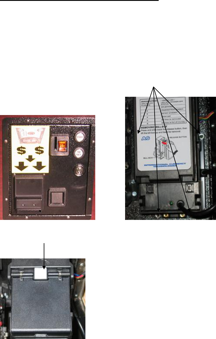
(IX)
Removing Dollar Bill Acceptor (DBA) and/or Stacker
1. Open the Bill Acceptor Access Door (FIGURE 4).
2. Disconnect the connector to the right of the DBA.
3. Remove the four nuts (FIGURE 5).
4. DBA is now ready to remove.
5. Reverse process to re-install.
6. To remove stacker slide the white square (FIGURE 6) out and stacker lifts
up and out. To replace stacker just reverse process and stacker snaps in place.
Bill Acceptor The Four Nuts
Access Door
FIGURE 4 FIGURE 5
White Square
FIGURE 6
Page 9

(X)
Great 8 Chip Replacement & Startup
Open the Bill Acceptor Access Door (FIGURE 7) and Disconnect the Battery.
Bill Acceptor Link LK3 U1 Chip Access
Access Door Button
FIGURE 7 FIGURE 8
Locate link LK3 on the left circuit board, (FIGURE 8) & remove the shorting link from the two pins.
Locate U1 on the left circuit board. Remove and replace with new program chip. (Make sure the notch
molded into one end of the chip is closest to the access button & that no pins are bent under.)
Replace the LK3 link onto the two pins (FIGURE 8).
Connect the two battery leads making sure to connect the yellow wire to positive (+) & the black wire to
negative (-). The display should now display the default time & rack costs, & the "heartbeat" asterisk (*)
should be flashing in the lower right hand corner of the LCD display.
If the display is not as described:
Double-check the battery connections.
Check to insure the Chip U1 is properly installed.
Disconnect the Positive battery lead & wait 10 seconds. Re-connect lead.
To test, insert a bill into the DBA. NOTE: there will be a slight delay before the DBA wakes up and the
bill is accepted. The display will show “Checking Bill”.
NOTE: ALL DATA HAS BEEN LOST ! ! ! The Day & Time will have to be set and if the settings
were changed from the original defaults, follow the “Setup of Operating Values” (Page 2)
procedure to customize the program.
Page 10

(XI)
Additional notes about the new program and “On Board” Charger
1. When play is in progress, the program may be reset by pressing
the access button. Any time or rack credits will be lost but the
stored totals will be correct.
2. When the battery needs recharging the display will show the message:
LOW BATTERY
USE PUSH CHUTE
To clear this message you MUST press the START button next to the Dollar Bill
Acceptor. Once the message has been cleared you may insert a bill into the
Dollar Bill Acceptor to double-check the battery condition. If the battery is low,
the Low Battery message will re-appear. Then re-charge your battery.
3. Any time bills are accepted by the bill acceptor, the 4 hour credit cancel
timer is started. Each time a rack of balls is released this timer is reset to
4 hours. At the end of 4 hours with no activity, the program will be reset.
This will cancel any credit (money, time or racks). If money credit was
not assigned to Rack play or Time play, this will not be reported on the
Rack or Time Stored Totals, but it will be included in the Running Total.
4. Any credit remaining will be shown on the display. (CREDIT $ N.NN)
5. If the coin meter is left unplugged, the DBA will be disabled.
Normal operation may be restored by re-connecting the coin meter.
6. The “On Board” Battery charger is installed in the table behind the ball return. To
charge the battery (Using the On Board Charger) at the location. Simply plug an
extension cord into the 3-prong receptacle. Receptacle is located underneath the
table at the Ball Return end near the center of the table. (NOTE: Table is designed
to run off of a Battery NOT just the charger alone !) Running the table with
only the Charger is not recommended and could damage the electronic part of the
table. The charger that will be inside the table is a 12 Volt 1000mA for sealed Led
Acid batteries. To charge a 12 Amp Hour battery that is completely dead should
take about 24 hours.
Page 11

(XII)
Schematic of Board in Figure 2 or 8
Page 12

(XIII)
Page 13
(XIV)
TROUBLE SHOOTING GUIDE
The ICT DBA runs off of a 12-volt battery. To extend battery life the DBA is in “Sleep
Mode” until a bill is inserted. When a bill is inserted into the DBA the two LED’s will
flash (There is a slight delay until the DBA is in “Wake Mode”) which tells you that the
DBA has been activated. Also, the LC Display will show the words “Checking Bill”.
Insert bills into the DBA and receive credit to play the game. If you are not able to insert
bills and receive credit, see the following suggestions listed below.
If the ICT DBA will not take dollar bills, check the follow situations.
Display reads: LOW BATTERY
USE PUSH CHUTE
1. The battery is below 11 Volts and needs charging.
a. Using the “On Board” Charger:
After the battery is charged (Charging at least 24 hours or until the Green
Light on the charger comes on) press the “Start” button next to the Dollar
Bill Acceptor to clear the display message. If the display does not clear
the low battery message, then unplug the wire going to the Positive
Terminal of the battery for 5 seconds then plug back on. Since the battery
was unplugged, go into “Setup” and check the “Day” and “Time” and
adjust appropriately. The rest of the program will not be affected. Test the
table by inserting dollars and vend the pool balls to insure proper
operation.
b. Swapping out the Battery:
Unplug the battery and replace it with a completely charged battery.
Plug the black wire to the Negative Terminal first then the Red or Yellow wire to the
positive terminal second. Check display for blinking “ * ”. If the battery was unplugged for
longer than 10 minutes check “Time” and “Day” in “Setup”. All other settings will not be
affected.
If the LED’s do not flash on: 1. Battery may be low. Check out the table
with a fully charged battery. If the table now works, change
the battery.
If the LED’s do flash check the ICT Manual for error or reject codes page 4.
If the LED’s do not flash:
1. DBA may be locked out because there are credits on the display and a game is selected.
2. Coin Meter may be disconnected, if so, connect coin counter and try again.
Page 14
3. Pool balls will not vend using the “Start” button:
1. Make sure the game has credits on the display and a game has been selected (Rack or
Time Play) using the Time/Rack button.
2. Check to insure that all connectors are seated properly on both the Valley/Dynamo red
and Coin boards. Mainly, J2 on the Valley/Dynamo red board (lower right hand corner).
If loose, reseat connector and try again.
3. Check to see if the Start button switch is properly mounted in the holder.
4. Check the wires going to the start button to insure the wires are not damaged.
5. Check to see if the Start button is wired in the normally open position.
6. Try using the Push Chute to vend balls. If the balls vend via the Push Chute, then check
the motor function.
Motor Function:
1. Make sure the game has credits on the display and a game has been
selected (Rack or Time Play) using the Time/Rack button. Activate the Start button while
the Push Chute Door is open so that you can observe the motor movement. NOTE: DO
NOT TURN MOTOR BY HAND OR PULL ON CABLE. DOING SO MAY
DAMAGE MOTOR!
a. If the motor cycles, but does not vend the pool balls:
1. Check to insure the cable has not come off of the motor shaft arm.
2. Check to insure the cable has not come off of the trip rod.
3. Check to insure the “8” hook on the motor shaft arm is not
damaged.
4. Check to insure the Eye Bolt on the trip rod is not damaged.
5. Check to insure the cable is not damaged or broken.
b. If the motor does not cycle when the start button is pushed:
1. Battery may be low. Check with fully charged battery. If the
motor now works, change the battery.
Page 15
2. Check to insure the wires have not come loose from the motor.
(Yellow wire on the top and Black wire on the bottom of motor.)
3. Check to insure the wires have not come loose from the motor
switch. (Wired in the normally open position.) SEE Page 12,
Motor Assembly.
4. Motor may be broken or bad. Replace with known good motor.
LC Display is blank (Nothing on the display).
1. Battery may be low. Check out the table with a fully charged battery. If the LCD now
works, change the battery.
2. If battery connections are loose, disconnect connectors from the battery and tighten
connectors with pliers. Reconnect battery.
3. Check the Link LK3 to insure that the link is properly seated.
a. If the link is loose, remove the link and spread link posts so that the link will not
be loose when the link is put back. Reconnect link. Disconnect battery for 10
seconds and reconnect.
4. Check the harness connector connection J3 (on the Valley/Dynamo red board) to make
sure the connector is seated correctly.
a. If the connector is loose, reseat connector. Disconnect battery for 10 seconds
and reconnect.
5. Check the harness connector connection on the LCD display board to make sure the
connector is seated properly.
a. If the connector is loose, reseat connector. Disconnect battery for 10 seconds
and reconnect.
6. Visually inspect the LCD to make sure the display is not cracked. If the display has
some dark purple liquid under the glass you more than likely have a cracked display and
will have to replace the display.
Page 16

(XV)
FIGURE 9 – part # 20600046 FIGURE 10 – part # 20600044
DANGER:
If Push Chute Door is changed be aware of the different style of Push Chute Extensions!
FIGURE 9 shows the CORRECT Push Chute Extension for the Great Eight!
FIGURE 10 Shows the WRONG Push Chute Extension for the Great Eight!
FIGURE 9 shows the ONLY Push Chute Extension to be used in the Great Eight because of the
configuration of the motor to vend the pool balls, and the ONLY Push Chute Extension currently available
for tables Model ZD-4 to present.
FIGURE 10 shows the Push Chute Extension that Valley had used from the ZD-4 to the ZD-8. It is
discontinued and no longer available.
NOTE: Swapping doors with the Push Chute Extension shown in FIGURE 10 will cause MOTOR
DAMAGE.
Page 17

(XVI)
Valley-Dynamo Great8 Software Timing Addendum
If you are using an IC on your main board that is geared toward resolving time keeping issues, please use
this document to “fine tune” the system clock. Fine tuning may be necessary depending on certain system
environments.
1. Start by performing the usual steps to enter the System Configuration Menu
a. Press and hold down the ACCESS button until the system is showing “5 4 3 2 1 Setup” on
the display: DO NOT let go of the ACCESS button at this point or you will enter the game
configuration menu as usual
2. With “5 4 3 2 1 Setup” displayed, press and hold down the VALUE button so that both buttons are
being held down
3. You are taken into the clock configuration menu
a. If the clock configuration menu does not display, you do not have an IC with the Time
Configuration utility. Contact your support department for an updated IC.
b. When you enter the clock configuration menu, DO NOT let go of the ACCESS and
VALUE buttons yet. This screen acts like a stop watch screen. When you let go of the
buttons, the timer begins to count and you can use a stop watch or some other timing device
to find the setting appropriate for your environment. The default value is 35, and can
navigate between 0 (slowest) to 99 (fastest)
4. When you are ready to compare the system time to your own clock/stop watch, release both the
ACCESS and VALUE buttons and the system starts counting
5. Use the Time/Rack button to increase the value (speed up the clock)
6. Use the Start button to decrease the value (slow down the clock)
7. When you are comfortable with your choice, press the ACCESS button to exit the clock
configuration menu
8. You will now have to set the time using the normal system configuration menus
9. To restart the Time Configuration utility, go back to step 1
Page 18

(XVII)
GREAT EIGHT OPERATING INSTRUCTIONS
1. Insert Money
NOTE: No Change Given
2. Choose RACK or TIME PLAY
By pushing the
TIME / RACK START
Button
3. Press the START
Button (Next to the TIME
Dollar Bill Acceptor) RACK
to release the balls
To START and STOP the SPEED POOL Timer
Press the TIME / RACK TIME
Button next to the Dollar RACK
Bill Acceptor
Or the START Button START
next to the Q-Ball Return
Page 19

Today's Date
not set
Today's Time (24hr)
not
set
not
set
DBA Table
Setup Defaults
This sheet reflects the default
values on the table.
hrs
min
Normal Price-per-Game
$1.00
Happy Hour 1 Price-per-Game
$0.75
Happy Hour 2 Price-per-Game
$0.75
Price for 30 minutes
$5.00
Credit Level 1 Price
$5.00
Total Games at Credit Level 1
5
Credit Level 2 Price
$10.00
Total Games at Credit Level 2
10
Time Bonus
5
Sunday
Monday
Tuesday
Wednesday
Thursday
Friday
Saturday
Happy Hour 1 Start (24hr)
16
00
16
00
16
00
16
00
16
00
16
00
16
00
Happy Hour 1 End (24hr)
16
00
16
00
16
00
16
00
16
00
16
00
16
00
Happy Hour 2 Start (24hr)
16
00
16
00
16
00
16
00
16
00
16
00
16
00
Happy Hour 2 End (24hr)
16
00
16
00
16
00
16
00
16
00
16
00
16
00
hrs
min
hrs
min
hrs
min
hrs
min
hrs
min
hrs
min
hrs
min
Happy Hour interval will not take place because all times are set equal
Page 20

Today's Date
1
Today's Time (24hr)
2
3
DBA Table
Setup Worksheet
Number in the lower-right corner of
each box indicates the
corresponding programming
parameter
hrs
min
Normal Price-per-Game
4
Happy Hour 1 Price-per-Game
5
Happy Hour 2 Price-per-Game
6
Price for 30 minutes
7
Credit Level 1 Price
8
Total Games at Credit Level 1
9
Credit Level 2 Price
10
Total Games at Credit Level 2
11
Time Bonus
12
Sunday
Monday
Tuesday
Wednesday
Thursday
Friday
Saturday
Happy Hour 1 Start (24hr)
13
14
21
22
29
30
37
38
45
46
53
54
61
62
Happy Hour 1 End (24hr)
15
16
23
24
31
32
39
40
47
48
55
56
63
64
Happy Hour 2 Start (24hr)
17
18
25
26
33
34
41
42
49
50
57
58
65
66
Happy Hour 2 End (24hr)
19
20
27
28
35
36
43
44
51
52
59
60
67
68
hrs
min
hrs
min
hrs
min
hrs
min
hrs
min
hrs
min
hrs
min
If Happy Hour times are set equal, the interval will not take place. If times are both set to "o", Happy Hour will continue for the full 24 hours
Page 21
