
1
GEN11005-L
The Power of Fields and Attributes in AutoCAD
Dhanjeet Sah
PTW Architects – Sydney, Australia
Learning Objectives
1. Learn how to create attributes and redefine existing attributes
2. Learn to insert fields, insert field with text/mtext, or use with attributes
3. Learn to use fields for complex calculation using elements property combining with formulas
4. Learn how to extract attribute/fields from the design data and output as AutoCAD Table or
export as Excel or database file
Description
Have you imagined how powerful attributes and fields can be in your design process? Learn how to add
intelligence to your design data using fields and attributes. You will learn how to define and redefine
attributes, using fields with text/Mtext and attributes. See how quickly you can use fields to extract
properties of elements and combine them with formulas for complex calculations. You will also learn
how to extract attribute/fields from the design data and output as AutoCAD software Table or export as
a Microsoft Excel or database file.
About the speaker
Dhanjeet Sah has background with 17 years of industry experience, mentoring industry professionals in
adopting BIM/CAD/CG techniques to set up real-world production pipelines and workflows while
integrating multiple applications for a specific task. He has also worked for numerous projects from
Design, Visualization, 3D Animation/ Compositing to CAD/BIM Consulting for various multinationals and
government organizations. He is working as a BIM Manager at PTW Architects and his main role is
provide consulting, support and training services to develop workflows to achieve higher levels of
collaboration and efficient design through the use of AutoCAD, Revit, Navisworks, 3ds max, other
applications/technologies to their staffs. He is also an AutoCAD, Autodesk Revit Architecture & 3ds max
(since 3ds max 4) certified professional/Instructor from Autodesk Inc. He has instructed as Autodesk
Certified Trainer for AutoCAD, 3ds max and Revit in Autodesk Training Centre in different countries; this
includes Singapore, UAE, Nepal and Australia.
Email: dhanjeetsyd@gmail.com

The Power of Fields and Attributes in AutoCAD
2
About Attributes
In AutoCAD you can create geometry such as lines, circles, arc etc. You can also add things such as text,
hatch and dimensions to annotate the drawings. AutoCAD is also a database of information. Most of
that database contains the information for reproducing what you have drawn, but you can also add
information that is non-graphical. One of the easiest ways of adding non-graphical information is to use
attributes. An attribute is text that can be attached to a block to convey more information than just the
geometry on its own could convey.
Attribute data can also be easily extracted to an external file such as an Excel spreadsheet or database
or placed as a table within the drawing. This makes it easy to gather information for a Bill of Material or
Parts List.
F
IGURE
1:
E
XAMPLE OF
A
TTRIBUTE
Note: It is important to make sure that attribute tags have unique names. The Enhanced Attribute Editor
will display any duplicate tags in red. Duplicate tags will cause problems when extracting data or if you
use them in dynamic blocks.
About Defining Attributes
Attributes are defined using the Attribute Definition dialog, ATTDEF or AT command at the command
prompt. One can also find commands to Define, Edit and Manage attributes on the Insert tab of the
Ribbon.

The Power of Fields and Attributes in AutoCAD
3
There are three components to an attribute definition:
A unique tag that identifies the attribute by name
A prompt that can be displayed as the block is inserted
A default value that is used if a variable value is not entered at the prompt
When one defines an attribute one specifies its features, such as an identifier, an initial value, its
appearance, its location relative to the associated block, as well as other properties.
The attribute becomes part of a block definition, and when one inserts an attributed block into a
drawing, the attributes are also inserted.
An attribute’s value can be the same or different for each insertion of the block depending on
how the attribute was defined. Additionally, a block can have multiple attributes.
Attribute Definition Dialog Box
F
IGURE
2:
A
TTRIBUTE
D
EFINITION
D
IALOG BOX
Defining the Attribute
1. Open the drawing “AU_2015_GEN11005-L_Start.dwg”
2. Type ATTDEF at the Command prompt or from the Ribbon ‐> Insert tab ‐> Block Definition
panel, select Define Attributes and enter the attributes as shown below.

The Power of Fields and Attributes in AutoCAD
4
F
IGURE
3:
D
EFINE
A
TTRIBUTE
O
PTION
Tag- ITEM
Prompt: Enter Item Number
Value: BS001
Text Height: 70
3. Click ok and place as shown in Fig 4.
F
IGURE
4:
B
ASIN
A
TTRIBUTE
4. Repeat for
COST
&
MAKER
ATTRIBUTE
5. Once Attributes are defined, let’s make BLOCK
o Enter B or BLOCK on command prompt and press enter
o Enter details as shown in the dialog box;
o E
NTER
B
LOCK
N
AME
=
B
ASIN
o Click on “Pick Point” and then select Mid of Basin as shown in Fig 5.
o Click on “Select Object: and select all objects that forms basin including Attributes

The Power of Fields and Attributes in AutoCAD
5
F
IGURE
5:
B
LOCK
D
EFINITION
a. C
LICK ON
“OK”.
b. E
NTER
ITEM
=“BS001”,
COST=120
&
M
AKER
=
AU
2015
AND CLICK
“OK”.
Insert Block and define values
1. Enter Insert command or go to INSERT Tab then click on “Create Block”.
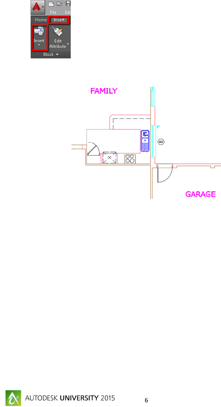
The Power of Fields and Attributes in AutoCAD
6
2. Select “Basin” from list and then Place in the Kitchen Top as shown in fig 6. with the values
required.
F
IGURE
6:
I
NSERT
L
OCATION OF
B
LOCK
3. Repeat the INSERT to place if you want to continue placing same block elsewhere with different
values as required.
Note:
ATTDIA (System Variable) - Controls whether the INSERT command uses a dialog box for
attribute value entry or whether one is prompted for the values at the Command prompt. This variable
is saved in the Windows Registry and once set remains that way for all drawings until changed.
Default value = 1 (uses a dialog), setting this value to 0 (zero) issues a Command prompt.
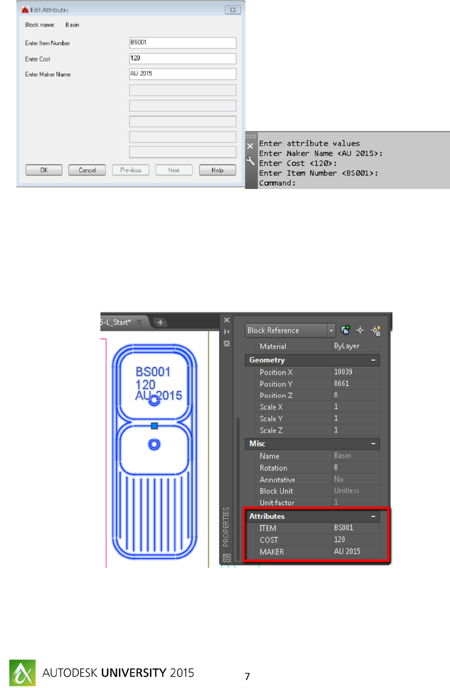
The Power of Fields and Attributes in AutoCAD
7
Modifying Attributes Value
There are few ways to change value of Attributes:
1. Using PROPERTIES PALATTE
o Select Basin and then change the Value from Properties Palette as shown in Fig 7
F
IGURE
7:
E
DIT
A
TTRIBUTE USING
P
ROPERTIES
P
ALETTE
2. D-click on block or enter “EATTEDIT” on command prompt and then change value as shown in
fig 8.

The Power of Fields and Attributes in AutoCAD
8
F
IGURE
8:
E
NHANCED
A
TTRIBUTE
E
DITOR
3. BATTMAN – this command edits attributes and properties in the block, similar to the
EATTEDIT command, but in all block definitions. In other words, it makes global changes to all
insertions of a single block. Additionally, it allows one to add or remove attributes, as well as
reorder them.
Redefine Blocks with Attribute
Use one of the methods.
1. Explode block, Add new attribute and then convert the block with same name. You will be then
prompted to Redefine Block.
2. Select Basin and then R-click and click “Block Editor”. In this block editor, you can add/remove
attribute and then click on CLOSE button.

The Power of Fields and Attributes in AutoCAD
9
You will be prompted with “Block- Changes Not Saved” dialog box. Click on “Save the changes to
Basin.
You may not see the changes immediately and hence we have to Synchronize the block using
command ATTSYNC or Insert > Synchronize as shown in Fig 9.
F
IGURE
9:
Synchronize

The Power of Fields and Attributes in AutoCAD
10
Fields:
A field in text contains instructions to display data that you expect to change during the life cycle of a
drawing.
When a field is updated, the latest data is displayed. For example, the value of the FileName field is the
name of the file. If the file name changes, the new file name is displayed when the field is updated.
Fields can be inserted in any kind of text (except tolerances), including text in table cells, attributes, and
attribute definitions. When any text command is active, Insert Field is available on the shortcut menu.
Examples are the current date, the drafter’s initials, the company name and address, and so on.
Change the Appearance of a Field
The field text uses the same text style as the text object in which it is inserted. By default, fields are
displayed with a light gray background that is not plotted FIELDDISPLAY.
Let’s create CUSTOM FIELDS:
1. You use the Drawing Properties feature to create custom properties. Choose the Application
button> Drawing Utilities> Drawing Properties or choose File>Drawing Properties to open the
Drawing Properties dialog box.
2. Click the Summary tab. If you can use any of these properties, start here. For example, you can
use the Title field for the drawing name.
3. To add a custom field, c lick the Custom tab. Use a custom field for content that cannot use one
of the fields that come with AutoCAD.
4. Click the Add button. In the Add Custom Property dialog box, enter a field name and Value and
click OK.

The Power of Fields and Attributes in AutoCAD
11
Enter: Project Name = AU2015 Home
Client Name: AU 2015
Insert fields
5. Open the drawing “AU_2015_GEN11005-L_Fields.dwg”
6. Activate Layout “A101”.
7. Make Text Style = ST2mm as shown in Fig 10
F
IGURE
10:
8. Go to INSERT tab and then click on Field
9. Select “Project Name” from the field list and place as shown in Fig 11.

The Power of Fields and Attributes in AutoCAD
12
F
IGURE
11:
C
USTOM
F
IELDS
10. Repeat same step as 5 to insert CLIENT NAME.
11. You could also exercise to insert fields to insert as many you could to annotate the drawings.

The Power of Fields and Attributes in AutoCAD
13
Insert Fields using Single Line Text or MText
1. Make Text Style = ST6mm as current
2. Create a Single Line Text or MText
3. R-click in the editor then click on Insert Field.
4. Select “SystemVariable” in the left pane, select CTAB and click OK to insert Sheet number that
corresponds to Layout name.
5. This process can be repeated for all other Layouts.
6. Rename Layout as A101 to A101-2015.
7. Enter RE or REGEN on command prompt to regenerate drawing that updates the fields.

The Power of Fields and Attributes in AutoCAD
14
8.
Area Calculation using Fields
1. Open the drawing “AU_2015_GEN11005-L_Area.dwg”
2. Click on Isolate Layer and then click on Pline as shown in Fig 12.
F
IGURE
12:
I
SOLATE
L
AYER

15
3. Change Text Style = STYLE 1. Create Text using Single line or MText.
4. R-click in text editor, R-click and then click Insert Filed.
5. Select Object from left panel, click on and select PLINE as shown in Fig 13.
F
IGURE
12:
6. Change the Precision = 0.00
7. Click on Additional Format and then enter 0.000001 in Conversion Factor and SQ M in Suffix.
Use backspace if you want to leave space after the value is appeared.
8. Click OK and then OK again. This step will insert Area values from the select enclosed polyline.
9. Repeat the steps to create area for other rooms.
Area Calculation using Fields and formulas
1. Go to ANNOTATE > Tables > Table
2. Click on From Object data in the drawing and then OK

The Power of Fields and Attributes in AutoCAD
16
3. Select “Create a new data extraction”. And then click on NEXT
4. Type AREA in name and click SAVE.
5. Click on “Select objects in current Drawing” and then click on to select all polylines. After
selecting all polylins, click NEXT.
6. Click NEXT
7. In the dialog box, in right pane- Uncheck all except Geometry and then in left pane uncheck
Global width.
8. Un-check Show Count & Name as shown in fig 13 (1 & 2)
9. R-click on AREA column and then click on Set Column Data format.

The Power of Fields and Attributes in AutoCAD
17
F
IGURE
13:
D
EFINE
A
TTRIBUTE
O
PTION
10. Select Data Type = Decimal Number, Format = Decimal and Precision 0.00
11. Click on Additional Format and then Type 0.000001 in conversion factor.
F
IGURE
14:
D
EFINE
A
TTRIBUTE
O
PTION

The Power of Fields and Attributes in AutoCAD
18
12. Click NEXT and then check Insert data extraction table and output data to external file if you
want to save this output as excel table.
13. Select ROOMModel in Table style if there is different name and click NEXT
14. Click FINISH and then insert table in model space near to drawing.
15. Select end of the Row no 12 and then R-click ROWS> Insert Below to insert a new row as shown
in Fig 15.
F
IGURE
15:
D
EFINE
A
TTRIBUTE
O
PTION
16. Select cell A13, R-click and then Locking > Unlocked.

The Power of Fields and Attributes in AutoCAD
19
17. D-click on A13 and then R-click and select Insert Field.
18. In field dialog box, select Formula in field Name pane, click on SUM and select cells A3 to A12 as
shown in fig 16.
F
IGURE
16:
C
ELL
S
EELCTION
19. Select 0.00 in Precision and then click OK.
20. These steps calculates sum of areas from cell A3-A12.
Modify design and update Table.
21. Stretch one of the Top-right Polyline as shown in Fig 16.

The Power of Fields and Attributes in AutoCAD
20
22. The data extraction table has to be updated to reflect with values in new area and formulas.
23. Select Table, R-click and then click Update Table data Link.
24. You will see the new values reflected in the table.
Conclusion:
Attributes can be very simple to very powerful feature of AutoCAD. Combining fields with attributes,
allowing formulas with in field also can enhance your design & documentation. Further information
can always found on pressing F1 or typing command Help.
