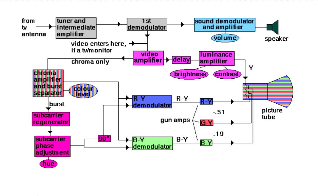
Block diagram of color TV receiver: A colour TV receiver contains all the necessary circuits of a
monochrome receiver plus additional circuits required for the reproduction of a coloured picture. A colour TV
receiver is basically a monochrome receiver with a decoder for colour signals and a colour picture tube.
block diagram of color television receiver
The color tv receiver consist of the following sections:
o Radio Frequency (RF) Tuner
o IF amplifier
o Video Section video amplifier
o PAL decoder / Color Processing section
o Synch Section
o Sound Section
o deflection and sweep circuits
o HT sections.
RF Tuner: It consists of VHF (Very High Frequency) and UHF (Ultra High Frequency). It selects the desired
T.V Channel and provides constant values of PIF = 38.9 MHZ and SIF = 33.4 MHZ. The purpose of the tuner
unit is to amplify both sound and picture signals picked up by the antenna and to convert the carrier frequencies
and their associated bands into the intermediate frequencies and their sidebands. The receiver uses

superheterodyne principle as used in radio receivers. The setting of the local oscillator frequency enables
selection of desired station
Video section: It consist of video detector which provides composite colour video signal (CCVS).This CCVS
consist of pure video, synch pulses, colour signals, colour bus, AGC bias is also obtained from this section.
PAL Decoder / Color Processing section: It consist of colour demodulator which provides demodulated U
and V signals. PAL decoder provides R.G.B signals. Where, R- Red, G-Green, B-Blue. Which are applied to
picture tube and PAL decoder also consist of ACC (Automatic Colour Control) and colour killer circuit.
Synchronization Section: This section provides horizontal and vertical synchronize pulses. It also provides
colour bus which is used as trigger signal to generate CSC (Colour Sub carrier) signal. The horizontal and
vertical pulses are applied to deflection coils of PT (Picture tube).The horizontal signal is also used to generate
EHT (Extra high tension) supply of about 25Kv.
Sound section: The output of FM (Frequency Modulator) detector is processed and the audio signal is
reproduced by the speaker. The sound is usually taken off before the video detector in colour sets, and a separate
converter is used for it, instead of taking it from the video detector. The reason that this is done is to minimize
a 920 KHz beat signal that can result between the 3.58 MHz colour subcarrier and the sound carrier signal. This
signal would show up as interference in the television picture.
HT section. (DC power supplies): Various DC sources needed in a typical television receiver are:
1. Low voltage: about 12 to 35 volts for IC and small signal amplifiers
2. Medium voltages: about 150 v for horizontal output stage, 300 to 400v for the screen and focus grid of
picture tube and about 175 v for the video amplifier
3. High voltage: 15 to 18KV for final anode of picture tube
Chroma decoder: The main function of chroma decoder is to recover U and V colour difference signals which
are combined with Y to obtain R, G and B video signal. For this the decoder has to perform following
Functions:
Chroma signal separation and amplification
Separation of U and V
Demodulation of U and V
Generation of subcarriers for two demodulators

Sync separation and processing: The horizontal and vertical sync pulses that form part of the composite video
signal are separated in the sync separator. A sync separator is a clipper that is suitably biased to
produce output, only during sync pulse amplitude of the video signal. The pulse train as obtained from the sync
separator is fed simultaneously to a differentiating and an integrating circuit. This results in occasional wrong
triggering of the horizontal oscillator which results in diagonal tearing of the reproduced picture. To overcome
this difficulty, a special circuit known as automatic frequency control (AFC) circuit is employed. The AFC
circuit employs a discriminator arrangement which compares the incoming horizontal sync pulses
and the voltage that develops across the output of the horizontal deflection amplifier.
The final circuit that must be considered is the color killer. This circuit is used by the Color Television Receiver
Block Diagram to prevent video voltages received in a black-and-white program from entering the chroma
amplifier. If they were amplified, the result would be the appearance of random color voltages, or confetti,
which would clearly be unwanted. The function of the color killer is to disable the chroma amplifier by cutting
it off during monochrome reception. It is done by noting the presence or absence of the color burst and acting
accordingly.
The only difference between black and White Television set and colour Television set is the IF circuit is the
importance of bandwidth for colour receivers. Remember that video frequencies around 3.58MHz just show
details in monochrome, but these frequencies are essential for colour information. Without them, there is no
colour. This is why the fine-tuning control on colour television sets must be tuned exactly, or else the colour
disappears, along with the higher resolution. The two main circuits that distinguish a colour TV receiver from
a monochrome are the colour picture tube and the chroma section containing the colour circuits.
