
Solar Power Technologies
for Future Planetary Science Missions
December 2017

Solar Power Technologies
for Future Planetary Science Missions
Strategic Missions and Advanced Concepts Office
Solar System Exploration Directorate
Jet Propulsion Laboratory
for
Planetary Science Division
Science Mission Directorate
NASA
Work Performed under the Planetary Science Program Support Task
December 2017
JPL D-101316
Assessment Team
Jet Propulsion Laboratory, Caltech
Rao Surampudi (Chair)
Julian Blosiu
Paul Stella
John Elliott
Julie Castillo
Goddard Space Flight Center
Thomas Yi
John Lyons
Glenn Research Center
Mike Piszczor
Jeremiah McNatt
Langley Research Center
Chuck Taylor
Johns Hopkins University Applied Physics
Laboratory
Ed Gaddy
Aerospace Corporation
Simon Liu
U.S. Army
Ed Plichta
NASA HQ
Christopher Iannello
Advisory Committee and Editors
Patricia M. Beauchamp
James A. Cutts
National Aeronautics and
Space Administration
Jet Propulsion Laboratory
California Institute of Technology
Pasadena, California

Strategic Missions and Advanced Concepts Office JPL D-101316
Solar Power Technologies for Future Planetary Science Missions ii
Foreword
Future planetary exploration priorities envisioned by the National Research Council’s (NRC’s)
Vision and Voyages for Planetary Science in the Decade 2013–2022,
1
developed at the request of
the NASA Planetary Science Division (PSD), seek to reach targets of broad scientific interest across
the solar system. Power systems are required for all of these mission concepts, but which power
system is optimal for a particular potential mission depends on the mission’s scientific and
operational needs and, in some cases, constraints imposed by NASA. Radioisotope Power Systems
(RPS) are extremely important options for many planetary mission types, particularly to the outer
reaches of the solar system and beyond, and the current capabilities and future technological
pathways for RPS have been extensively discussed and previously documented.
2,3
However, solar
power is used for the majority of planetary spacecraft and, as a complement to recent RPS studies,
this report assesses the capabilities and limitations of state-of-practice solar power systems and the
status of advanced solar power technologies, and it documents innovations needed for upcoming
mission concept scenarios. Although solar power has been used on most planetary missions to date,
it has limitations as missions seek to operate further away from the Sun or in Sun-shadowed regions.
Thanks in part to the commercial sector, there have been substantial advances in solar cell and solar
array technologies that have enabled some outer planet missions, such as Juno, to be accomplished
with solar power, which were long thought to be out of the reach of such technologies. Now we see
that even some mission concepts to Saturn are possible with current solar power technology. A
companion report assesses energy storage technologies for planetary missions because, in some
cases, missions may need primary batteries for power.
Patricia M. Beauchamp
Chief Technologist,
Engineering and Science Directorate
Jet Propulsion Laboratory,
California Institute of Technology
Pasadena, CA 91109
December 12, 2017
1
National Research Council, “Vision and Voyages for Planetary Science in the Decade 2013-2022,” The National
Academies Press, Washington, DC (2011). https://solarsystem.nasa.gov/docs/131171.pdf
2
John Hopkins University, Applied Physics Laboratory. 2015. Nuclear Power Assessment Study, TSSD-23122.
http://solarsystem.nasa.gov/rps/npas.cfm
3
Jet Propulsion Laboratory, California Institute of Technology. June 2017. Next-Generation Radioisotope
Thermoelectric Generator Study Final Report, JPL D-99657.

Strategic Missions and Advanced Concepts Office JPL D-101316
Solar Power Technologies for Future Planetary Science Missions iii
Acknowledgments
This work was conducted as part of the Planetary Science Program Support (PSPS) task that the Jet
Propulsion Laboratory carries out for the National Aeronautics and Space Administration’s
(NASA’s) Planetary Science Division. The research was carried out at the Jet Propulsion Laboratory,
California Institute of Technology, under a contract with NASA. Gordon Johnston is the NASA
program executive responsible for PSPS Task and Leonard Dudzinski is the program executive for
this work funded under the Technology subtask.
The content of this report is pre-decisional information and is provided for planning and discussion
purposes only.
Reference herein to any specific commercial product, process, or service by trade name, trademark,
manufacturer, or otherwise, does not constitute or imply its endorsement by the United States
Government or the Jet Propulsion Laboratory, California Institute of Technology.
Special gratitude is extended to Joel Schwartz, Andreea Boca, and the many individuals who
contributed their knowledge and time in preparation of this report. Special thanks to Mary Young
for the technical publications support during the report preparation and to Richard Barkus for
development of the cover. The authors would also like to acknowledge the valuable technical
information provided by solar cell and array manufacturers and aerospace companies (Spectrolab,
SolAero, mPower, Microlink, Alta Devices, Orbital-ATK, Deployable Space Systems, Inc.,
Lockheed Martin Astronautics, Boeing Defense, Space, and Security, and Sierra Nevada
Corporation), as well as by the Department of Defense and National Laboratories (Army Research
Laboratory, Air Force Research Laboratory, Aerospace Corporation, Navy Research Laboratory,
and Applied Physics Laboratory).
©2017. All rights reserved.
Other Reports in this Series (which can be found on https://solarsystem.nasa.gov)
Power Technology
• Advanced Radioisotope Power Systems Report, Report No. JPL D-20757, March 2001.
• Solar Cell and Array Technology for Future Space Missions, Report No. JPL D-24454, Rev.
A, December 2003.
• Energy Storage Technology for Future Space Science Missions, Report No. JPL D-30268,
Rev. A, November 2004.
• Energy Storage Technologies for Future Planetary Science Missions, Report No.
JPL D-101146, December 2017.
Planetary Protection Technology
• Planetary Protection and Contamination Control Technologies for Future Space Science
Missions, Report No. JPL D-31974, June 2005.
• Assessment of Planetary Protection and Contamination Control Technologies for Future
Science Mission, Report No. JPL D-72356, January 2012.
Extreme Environments
• Extreme Environment Technologies for Future Space Science Missions, Report No. JPL
D-32832, September 2007.
Guidance Navigation and Control
• Guidance, Navigation, and Control Technology Assessment for Future Planetary Science
Missions: Part I. Onboard and Ground Navigation and Mission Design, Report No. JPL
D-75394, October 2012.
• Guidance, Navigation, and Control Technology Assessment for Future Planetary Science
Missions: Part II. Onboard Guidance, Navigation, and Control, Report No. JPL D-75431,
January 2013.
• Guidance, Navigation, and Control Technology Assessment for Future Planetary Science
Missions: Part III. Surface Guidance, Navigation, and Control, Report No. JPL D-78106,
April 2013.

Strategic Missions and Advanced Concepts Office JPL D-101316
Solar Power Technologies for Future Planetary Science Missions iv
Table of Contents
Foreword ........................................................................................................................................................................ ii
Acknowledgments ......................................................................................................................................................... iii
Executive Summary ....................................................................................................................................................... 1
1 Study Overview ....................................................................................................................................................... 8
1.1 Introduction .................................................................................................................................................. 8
1.2 Objectives .................................................................................................................................................... 9
1.3 Approach ...................................................................................................................................................... 9
1.4 Schedule ...................................................................................................................................................... 9
1.5 Assessment Team ..................................................................................................................................... 10
1.6 Participants ................................................................................................................................................ 10
2 Space Solar Power Needs of Future Planetary Mission Concepts ....................................................................... 11
2.1 Introduction ................................................................................................................................................ 11
2.2 Outer Planetary Mission Concepts ............................................................................................................. 11
2.3 Inner Planet Mission Concepts................................................................................................................... 13
2.4 Mars Mission Concepts .............................................................................................................................. 16
2.5 Small Body Mission Concepts .................................................................................................................... 18
2.6 Summary .................................................................................................................................................... 20
3 State-of-Practice Solar Cell and Array Technology ............................................................................................... 21
3.1 Introduction ................................................................................................................................................ 21
3.2 State-of-Practice Space Solar Cells ........................................................................................................... 22
3.2.1 Device Technology ........................................................................................................................ 22
3.2.2 Current Production Solar Cells ...................................................................................................... 22
3.2.3 Solar Cell Assemblies .................................................................................................................... 23
3.3 State-of-Practice Solar Arrays .................................................................................................................... 25
3.3.1 Body-Mounted Solar Arrays ........................................................................................................... 25
3.3.2 Deployable Rigid Solar Arrays ....................................................................................................... 26
3.3.3 Deployable Flexible Solar Arrays ................................................................................................... 27
3.3.4 Concentrator Solar Arrays ............................................................................................................. 29
3.4 Summary .................................................................................................................................................... 29
4 Advanced Solar Cell and Array Technologies ....................................................................................................... 30
4.1 Introduction ................................................................................................................................................ 30
4.2 Advanced Solar Cell Technologies ............................................................................................................ 30
4.2.1 Cell Efficiency ................................................................................................................................ 30
4.2.2 Planetary Mission Environments ................................................................................................... 35
4.3 Advanced Solar Array Technologies .......................................................................................................... 38
4.3.1 Flexible Arrays ............................................................................................................................... 38
4.3.2 Concentrator Arrays....................................................................................................................... 40
4.3.3 Specialized Planetary Mission Environments ................................................................................ 41
4.4 Infrastructure .............................................................................................................................................. 42
4.5 Summary .................................................................................................................................................... 43
5 Findings and Recommendations .......................................................................................................................... 44
5.1 Major Findings ............................................................................................................................................ 44
5.2 Recommendations ..................................................................................................................................... 45
5.2.1 Overall Recommendations ............................................................................................................ 46
5.2.2 Specific Recommendations ........................................................................................................... 46
6 Acronyms .............................................................................................................................................................. 47

Strategic Missions and Advanced Concepts Office JPL D-101316
Solar Power Technologies for Future Planetary Science Missions v
List of Tables
Table 2-1. Solar power system needs of the outer planet missions. ........................................................................... 13
Table 2-2. Solar power systems needs of inner planet mission concepts. .................................................................. 16
Table 2-3. Solar power system needs of the future Mars mission concepts. ............................................................... 18
Table 2-4. Solar power systems needs required for small body mission concepts. ..................................................... 20
Table 3-1. Solar Arrays on NASA Planetary Science Missions. .................................................................................. 21
Table 3-2. Current Production Triple-Junction Space Solar Cells. .............................................................................. 23
Table 3-3. Overview of Current Solar Array State-of-Practice. .................................................................................... 25
Table 4-1. Comparison of Proposed LIHT Cell and SOP Triple Junction Solar Cell. ................................................... 37
List of Figures
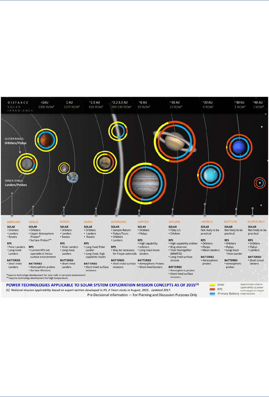
Figure 1-1. Approximate relative applicability of power technologies to target body mission concepts as of
2015, updated in 2017, showing solar power in yellow (outer rings for Orbiters and Flybys and inner rings
for landers and probes) ........................................................................................................................................... 8
Figure 2-1. Outer Planet Mission Destinations. ........................................................................................................... 11
Figure 2-2. Inner Planet Mission Destinations. ............................................................................................................ 13
Figure 2-3. Potential Venus aerial and surface mission concepts under consideration. ............................................. 14
Figure 2-4. Variation of pressure and temperature at various altitudes at Venus. ....................................................... 15
Figure 2-5. Simulated Solar Spectrum in Venus Atmosphere. .................................................................................... 15
Figure 2-6. Notional future Mars missions under consideration for the next decade and beyond. .............................. 17
Figure 2-7. Asteroids orbit the Sun in a tightly packed belt located between Mars and Jupiter. ................................. 18
Figure 3-1. Illustration of a Triple-Junction Solar Cell and Solar Irradiance Spectrum. Three n/p junctions
convert bands of successively longer wavelengths into electrical current. ........................................................... 22
Figure 3-2. Solar Cell Assemblies. Two versions of a solar cell assembly are shown. At left is a SolAero cell
incorporating a discrete bypass diode mounted in one corner. At right is a Spectrolab cell with a discrete
bypass diode mounted on the cell back side. ....................................................................................................... 24
Figure 3-3. Body-mounted arrays. From left to right: GOES 7 (NASA/NOAA) spinning satellite (illustration),
CP8 IPEX (Cal Poly Intelligent Payload Experiment, app. 10 cm × 10 cm × 10 cm), RACE (Radiometer
Atmospheric CubeSat Experiment). ...................................................................................................................... 26
Figure 3-4. Deployable Rigid Arrays. From left to right: Mars Exploration Rover with 1.2 m
2
array, Dawn
spacecraft (mission to Vesta and Ceres) with 36 m
2
array (illustration), Juno spacecraft (mission to Jupiter)
with ~43 m
2
array (illustration). ............................................................................................................................. 26
Figure 3-5. Flexible Fold-Out Arrays. Left: Illustration of Terra spacecraft with APSA based array.
Middle: International Space Station with eight flexible arrays and ~2500 m
2
total area.
Right: Cygnus resupply vehicle with UltraFlex array. ............................................................................................ 28
Figure 3-6. Flexible Roll-Out Array. The ROSA comprises a flexible photovoltaic blanket unrolled using
composite booms. ................................................................................................................................................. 28
Figure 4-1. Solar cell efficiency limits versus semiconductor bandgap. The solid lines are semi-empirical
limits for AM0 and AM1.5 illumination; the dashed line is based on thermodynamic considerations for
black body solar cells under AM0 radiation.
13
....................................................................................................... 30
Figure 4-2. Shortcoming of SOP Solar Cells. The bottom junction generates excess current at a low potential
due to its low bandgap (0.7 eV). ........................................................................................................................... 31

Strategic Missions and Advanced Concepts Office JPL D-101316
Solar Power Technologies for Future Planetary Science Missions vi
Figure 4-3. IMM Solar Cells. A 1.0 eV bandgap is added using the technique of inverted growth and
subsequent removal of the growth substrate. ....................................................................................................... 32
Figure 4-4. UMM Solar Cells. A 1.0 eV bandgap is added using lattice mismatched materials and buffer layers
to minimize propagation of crystal defects. ........................................................................................................... 33
Figure 4-5. Dilute Nitride Solar Cells. A 1.0 eV bandgap is added using materials that are lattice matched
to GaAs. Nitrogen in the 1.0 eV material is used to fine-tune the lattice constant. .............................................. 33
Figure 4-6. Semiconductor wafer bonding. Two separate wafers are bonded together to create single cell.
As a result, semiconductor quality is not affected by lattice mismatch. ................................................................. 34
Figure 4-7. Near-IR Absorbers. Quantum wells or quantum dots are used to extend the absorptance band of a
limiting junction. .................................................................................................................................................... 34
Figure 4-8. Flexible ultra-lightweight solar cells. Ultra-thin cells can be enabling for very large arrays, SEP
missions to the outer solar system and aero-vehicles.
,,
........................................................................................ 36
Figure 4-9. Power versus temperature for GaInP
2
cell. Performance at temperatures above 300°C is
severely limited for SOP cells. .............................................................................................................................. 36
Figure 4-10. Measured Solar irradiance spectrum on Venus. Solar irradiance decreases at lower altitudes
and energy at wavelengths below 600 nm is particularly diminished. ................................................................... 37
Figure 4-11. MegaFlex array. At left, a 10-m diameter MegaFlex demonstration unit was deployed in
ground test. At right is an illustration of a MegaFlex array on a flight system. ...................................................... 39
Figure 4-12. A2100 spacecraft. Flexible fold-out arrays based on the heritage ISS arrays, are in development
for the Lockheed Martin A2100 spacecraft bus. .................................................................................................... 39
Figure 4-13. Mega-ROSA. The Mega-ROSA comprises multiple ROSAs deployed from a central structural
spine.
21
.................................................................................................................................................................. 39
Figure 4-14. COBRA. The COBRA array is designed to provide compact stowage for SmallSat applications. .......... 40
Figure 4-15. Reflective Concentrator Technologies. (a) At left is a Cell Saver demonstration figure.
(b) Below is a FACT demonstration figure. Both use ~2× concentration to reduce the required quantity of
solar cells. ............................................................................................................................................................. 40
Figure 4-16. Refractive Concentrator Technologies. At left is an SLA demonstration figure. At right is a
SOLAROSA demonstration figure.. Both use flexible Fresnel lenses to achieve ~7–10×, up to 25× for the EESP
program for point focus Fresnel concentration. ..................................................................................................... 41
Figure 4-17. Martian Dust Mitigation Technology. At left is a technology utilizing electric fields for dust removal.
At right is a technology using piezoelectric actuators and mechanical vibration. .................................................. 42
Figure 4-18. Solar Probe Plus (Parker Solar Probe). This is intended to reach a distance of 0.046 AU from the
Sun. ...................................................................................................................................................................... 42

Strategic Missions and Advanced Concepts Office JPL D-101316
Solar Power Technologies for Future Planetary Science Missions 1
Executive Summary
Background
In order to plan effectively for the future, NASA’s Planetary Science Division requested an
assessment of the space solar power technologies required to enable/enhance the capabilities of
future planetary science mission concepts (>2025). The study report is organized into five major
sections: 1) study overview, 2) potential solar power system needs of future planetary science
missions, 3) capabilities and limitations of state-of-practice (SOP) space solar power systems,
4) status of advanced solar cell and array technologies, and 5) findings and recommendations.
Study Overview
The specific objectives of the study include: a) review the solar power system needs of potential
future planetary science missions, b) assess the capabilities and limitations of state of practice space
solar cell/array systems, c) assess the status of advanced solar cell/array technologies currently under
development and assess their potential capabilities and limitations, and d) identify and recommend
candidate solar cell and array technologies required for future planetary science mission concepts.
JPL assembled a technical assessment team to perform this study. The team consisted of subject
matter experts in the areas of mission planning, spacecraft power systems engineering, and space
solar power systems and technologies. The assessment team members were selected from NASA
(HQ, JPL-Caltech, GRC, LaRC, and GSFC), Aerospace Corporation, Johns Hopkins University
Applied Physics Laboratory (JHU-APL), and Department of Defense (DoD). The team met with
engineers and technologists from U.S. solar cell and array manufacturers, aerospace organizations,
and NASA mission centers to obtain information on the capabilities and limitations of the SOP
technologies. In addition, the team also met with several solar cell and array scientists and
technologists from universities, industry, NASA, DoD, and aerospace organizations to obtain
information on advanced solar cell and array technologies currently under development. The
assessment team held four meetings to: a) obtain information about potential next decadal planetary
science mission concepts and their power system needs, b) determine the capabilities of SOP space
solar power systems, c) assess the status and potential capabilities of advanced photovoltaic (PV)
power systems under development at various national laboratories, industry, and universities, and
d) summarize the findings and compile the recommendations.
Future Mission Concept Needs
Potential planetary science missions targeted for time period to be covered by the next decadal survey
(2023–2032) are grouped into four categories: a) outer planets b) inner planets, c) Mars, and d) small
bodies. The assessment team met with mission formulation study leads and power system engineers
from JPL, GSFC, Marshall Space Flight Center (MSFC), and JHU-APL to identify potential
planetary science missions that could be considered for implementation in the next 10–15 years and
determine the PV power system needs for solar powered mission concepts. The major findings of
the review team on the PV power system needs of these four groups of solar powered planetary
science missions are given below.
a) Outer Planet Missions
Radioisotope power systems are generally attractive for outer planet mission concepts because
RPS can be used in environments with limited or no sunlight. However, in some cases, solar power
systems are preferred compared to RPS due to performance, mass, or cost considerations. NASA’s

Strategic Missions and Advanced Concepts Office JPL D-101316
Solar Power Technologies for Future Planetary Science Missions 2
Juno mission is currently demonstrating the technical feasibility of using solar power at Jupiter
distance and the Europa Clipper mission has also baselined solar power.
Many planetary scientists are presently advocating two broad groups of outer planet missions for
future development: a) those to the Ice Giants—Neptune and Uranus, and b) those to Ocean Worlds
which include a number of moons of the outer planets with subsurface oceans of liquid water.
Potential Ocean World mission destinations include Enceladus, Europa, Titan, Ganymede, and
Callisto.
The major technical challenges for solar-powered outer planet missions are operation in extreme low
solar irradiance and low temperature environments. The solar irradiance at Jupiter (5.1 AU) is 3.7%
of that at 1 AU. At Saturn (9.5 AU) it is 1.1%, at Uranus (19.2 AU) it is 0.28%, and at Neptune
(30 AU) it is 0.1%. In view of these low solar intensities, missions would need solar arrays with high
power capability (>30 kW) at 1 AU to produce the required power (>500 W) at such large distances
(at >5 AU). In addition, Jupiter mission concepts require solar power systems that can operate in
high radiation environments. Other important requirements include long-life capability and high
reliability. Additionally, mission concepts using solar electric propulsion (SEP) would require high-
power solar arrays (>50 kW at 1 AU).
The major findings of the review team on the solar power systems required for outer planet mission
concepts to be considered in the next decadal survey are given below:
1. Ocean World missions require high efficiency (>38%), high voltage (>100 V) and high
power (>20 kW at 1 AU) solar power systems that can operate efficiently in low
irradiance, low temperature (LILT) environments. These missions would also require
solar power systems with low mass and volume. Missions to Jupiter and its moons
require solar power systems that can operate efficiently in high radiation environments.
2. The use of solar power systems for missions beyond Saturn (Ice Giants missions) is
highly challenging, and would require significant advances in solar cells and array
technologies to reduce mass and volume and improve operational efficiency and life
capabilities.
b) Inner Planet Missions
Inner planet missions to Venus and Mercury present quite different challenges for solar power
systems, because the power systems would need to operate in very close proximity to the Sun. The
Venus mission concepts under consideration for the next decade include: a) orbital missions,
b) variable altitude aerial platforms, and c) long-duration surface probes. The technical challenges
of the inner planet missions vary depending on the type of spacecraft (flyby, orbital, aerial, and
surface) and destination (Venus, Mercury). No missions to Mercury are presently under
consideration for the next decade or two.
Venus exploration mission concepts pose several challenges for solar power systems and they
depend significantly on the type of mission (orbital/surface/aerial). The temperature and pressure on
Venus ranges from 460°C and 90 bars at the surface, to a benign 0°C and 1 bar at an altitude of
55 km. In addition, very little sunlight reaches the Venus surface. There is very little atmospheric
motion near the surface. However, at 55 km altitude, the winds are strong enough to enable aerial
mission concepts, such as those with balloons.

Strategic Missions and Advanced Concepts Office JPL D-101316
Solar Power Technologies for Future Planetary Science Missions 3
The major findings of the review team on the solar systems required for next decadal Venus mission
concepts are given below:
1. Venus orbital missions can be implemented with existing solar power systems, as these
environmental conditions are relatively benign and are similar to those of Earth orbital
missions. However, future missions concepts would benefit from the use of high-
efficiency solar cells and low-mass solar arrays.
2. High-altitude aerial missions where solar fluxes are high and temperatures are benign
would require few solar power innovations except protection from the sulfuric acid
environment.
3. Low-altitude Venus aerial missions would require solar power systems capable of
operating in low solar irradiance (50–300 W/m
2
), high temperature (200–350°C), and
corrosive environments.
4. Solar cells required for these missions need to be optimized to operate efficiently under
the altered Venus surface solar spectrum.
Mercury orbital missions, such as NASA’s MESSENGER and the European Space Agency’s
(ESA’s) BepiColombo mission, required solar power systems that could operate in extremely high
solar intensities (1000–14000 W/m
2
) and high-temperature environments (~270°C).
c) Mars Mission Concepts
Although the NASA Mars mission roadmap is unclear after the 2020 launch of the next Mars rover,
Mars science mission concepts under consideration for the next decade include: 1) multi-functional
next-generation Mars orbiters, 2) potential Mars sample return missions (includes Mars ascent
vehicles, landers, and sample-fetching rovers), 3) Mars helicopters and other forms of proposed
aerial vehicles, and 4) human Mars precursor missions (large landers, rovers, demonstrations for in-
situ resource utilization). The major solar power system challenges for Mars surface missions are:
1) efficient operation of solar arrays under the Mars solar spectrum, 2) the complexity of deploying
and operating large photovoltaic arrays on rovers and landers, and 3) efficient operation of solar
arrays in Mars dust environments.
The major findings of the review team on the solar power systems required for next decadal Mars
mission concepts are given below:
1. Mars orbital missions do not present major challenges for solar power technologies and
can be implemented with SOP systems. However, future missions would benefit from
the use of high-efficiency solar cells and low-mass solar arrays.
2. Future Mars surface landers and rovers require solar cells capable of operating
efficiently under Mars solar spectral conditions. Since the effective solar spectrum at
the surface of Mars is depleted at short wavelengths, a cell designed to maximize the
efficiency in the red-shifted spectrum on Mars would optimize solar power for Mars
surface and aerial missions. Additionally, surface missions using solar arrays could
benefit greatly and reduce operational costs by incorporating dust removal capabilities.
3. Mars aerial missions would require high efficiency solar cells and low-mass solar arrays
since mass would be at a premium for helicopters and airplanes.

Strategic Missions and Advanced Concepts Office JPL D-101316
Solar Power Technologies for Future Planetary Science Missions 4
4. Future human precursor missions likely require low mass and high power arrays with
autonomous deployment capability. These missions also would require solar arrays
capable of operating efficiently in dusty martian environments.
d) Small Body Mission Concepts
Small bodies in our solar system include asteroids, comets, and dwarf planets, such as Ceres and
Pluto. Science priorities and potential mission recommendations, provided through community
white papers and the Small Body Assessment Group (SBAG), include the following: a) Near-Earth
Objects: Mega-multi-flyby, Multi-rendezvous, and Sample Return, b) Main belt asteroids and
Jupiter Trojans: Main Belt Sample Return, Multi-asteroid Rendezvous, and Jupiter Trojan
rendezvous, c) Comets: Comet Surface Sample Return and Comet Nuclear Sample Return, d) Small
Satellites: Phobos and Deimos Sample Return, e) Dwarf Planets: Flyby (rendezvous preferred), and
f) Centaurs and Trans-Neptunian Objects: Flyby (rendezvous preferred). Of particular interest is
solar electric propulsion, which is an attractive option for some, but not all small body mission
concepts.
The major technical challenges of the solar power systems required for small body missions are:
a) large solar arrays with low mass and low stowage volume (~2× lower than SOP), and b) long
operational life (>10 years).
The major findings on the solar power systems required for next decadal small body mission
concepts are given below:
1. Solar electric propulsion missions to small bodies would require high voltage (>100 V),
high power solar arrays (20–100 kW at 1 AU), with low mass and low stowage volume;
2. Missions to small bodies beyond 3 AU are similar to outer planet missions and would
require solar cells capable of operating in LILT environments.
State of Practice Solar Power Systems
This assessment team met with engineers and technologists from U.S. solar cell and solar array
manufacturers and user organizations, such as NASA mission centers, and from aerospace industry
to obtain information on the SOP solar cell array capabilities and their limitations. The major findings
on the capabilities and limitations on SOP space solar power systems cell and arrays are:
Solar Cells: Through the 1980s, spacecraft used primarily silicon solar cells with efficiencies
increasing from less than 10% to over 15%. During the 1990s, gallium arsenide (GaAs) solar cells
began to replace silicon solar cells, and progressed from single junction to dual junction cells that
were grown on germanium substrates (replacing the more expensive GaAs substrates). During the
2000s, triple junction solar cells became the standard for most space missions. Today’s space solar
cells offer efficiencies of ~30% at 1 AU along with resilience to radiation (electrons and protons).
Future solar cells are expected to reach efficiencies of ~38% at 1 AU by the mid-2020s.
Solar Arrays: The types of solar arrays currently in use are: a) body-mounted arrays, b) deployable
rigid arrays, and c) flexible fold out arrays. During the past 25 years, the specific power of solar
arrays has improved from 30 W/kg to 100 W/kg. In the past decade, these advances have enabled
several orbital and surface missions at Mars, as well as flyby and orbital missions to small bodies
and inner planets.

Strategic Missions and Advanced Concepts Office JPL D-101316
Solar Power Technologies for Future Planetary Science Missions 5
Limitations: In spite of these advances, SOP solar power systems are not attractive for the following
future planetary mission concepts:
1. Outer planetary missions beyond Saturn, because of limited performance capabilities at
low solar irradiance and low-temperature environments;
2. Low-altitude Venus aerial and surface missions, due to their limited operational
capabilities at high temperatures, high/low solar irradiance, and corrosive environments;
3. Long-duration Mars surface solar powered missions, because of dust accumulation on
solar arrays;
4. High-power, solar electric propulsion missions to small bodies and outer planets,
because such solar arrays would be heavy, bulky, and could not function in LILT
environments.
Advanced Space Solar Power Technologies
The assessment team met with several solar cell and array scientists and technologists from
universities, industry, NASA, DoD, and aerospace industry to obtain information on advanced solar
cell and array technologies currently under development. The major findings of the review team on
the status of advanced solar cell and array technologies are given below.
Solar Cells: High-efficiency solar cells are under development at several companies and universities
with support from DoD and private funding. NASA supports cell development through the Small
Business Innovation Research (SBIR) and other programs. The advanced solar cells architectures
under development include a) inverted metamorphic multi-junction (IMM), b) dilute nitride,
c) upright metamorphic, and d) semiconductor wafer bonding technologies (SBT). SBT refers to the
mechanical connection of one semiconductor wafer on top of another. Significant improvements in
solar cell performance are envisioned: a) near-term (1–2 years): >33% efficient, and b) mid- to far-
term (5–10 years): >37% efficient.
The IMM solar cells under development have an efficiency of approaching 35% at beginning-of-life
(BOL), 28°C, under the standard spectrum outside the Earth’s atmosphere (Air Mass 0 [AM0])
conditions. Space qualification of these types of cells is currently in progress. Development of dilute
nitride cells for space applications is also underway and efficiencies from 30–31% have been
reported
4
under the same conditions. To date, upright metamorphic multi-junction (UMM) solar
cells have an efficiency from 29–30% at AM0. SBT cells under development have an efficiency of
34–35% at AM0.
Limited work is currently in progress on the development of solar cells that can function: a) at low
5
solar irradiance and low temperatures (outer planet environments) and b) at high temperature,
high/low solar irradiance and corrosive environments of Venus. No identified research projects are
currently underway on the development of solar cells that can function effectively under Mars
spectral conditions, although research has been done in this area in the past.
6
Research into martian
dust removal has also been previously been studied but is not currently being pursued.
5
4
Suarez, Ferran, et al., “High Efficiency Multijunction Solar Cell Based on Diluted Nitrides”, Presented at 33rd
Space Power Workshop, Manhattan Beach CA (2015).
5
Boca, Andreea, et al., “Advanced-Architecture High-Efficiency Solar Cells for Low Irradiance Low Temperature
(LILT) Applications”, Proceedings of 44th IEEE-PVSC (2017).
6
Stella, Paul, et al., “Mars optimized solar cell technology (MOST)”, Proceedings of 33rd IEEE-PVSC (2008).

Strategic Missions and Advanced Concepts Office JPL D-101316
Solar Power Technologies for Future Planetary Science Missions 6
Solar Arrays: Several types of advanced solar arrays are under development with support from
DoD, commercial funding and NASA. Advanced solar arrays under development include: a) flexible
fold-out, b) flexible roll-out, c) concentrator, and d) solar arrays for extreme environments. Major
advances in solar array performance are envisioned: a) near-term: 150–200 W/kg, b) mid- to far-
term: 200–250 W/kg. A summary of the status of development of these advanced solar arrays is
given below.
Flexible Fold-out Arrays: UltraFlex is a flexible fold-out solar array from Orbital-ATK, Inc.
MegaFlex, currently under development in the same company, is an extension of their current
UltraFlex array to larger diameters and higher power. The MegaFlex deploys as a flexible fold-out
array with a circular geometry, similar to the UltraFlex. Deployment of a 10-m diameter MegaFlex
has been demonstrated in a ground test and is intended to reach diameters as large as ~30 m.
Flexible Roll-out Arrays: Roll-out solar arrays (ROSA) have been recently unfurled and
successfully tested at the International Space Station (ISS). Mega-ROSA is a flexible roll-out solar
array under development at Deployable Space Systems, Inc. (DSS). It represents an extension of the
ROSA to higher power. The Mega-ROSA comprises a set of multiple ROSAs deployed from a
central structural spine. The Mega-ROSA is intended to reach power capability exceeding 100 kW
at 1 AU, BOL.
Concentrator Arrays: Concentrator arrays offer a potential approach for mitigating the losses
associated with LILT conditions. Specifically, increasing the effective irradiance using concentrating
optics would allow solar cells in the outer solar system to operate as if they were much closer to the
Sun. Concentrator arrays that have undergone some development over the past decade include
a) Cell Saver Solar Array, b) Flexible Array Concentrator Technology (FACT), and c) Stretched
Lens Array (SLA). For outer planet mission concepts, one has to be careful that the amount of power
generated in Earth- or Venus-assisted trajectories to the outer planets does not overheat the arrays
and associated hardware. This is usually mitigated by feathering the arrays to reduce the solar
irradiance within the inner solar system. Novel ideas for concentrators are emerging, including
gossamer or very large collectors, and may have potential that could substantially alter the ability to
use solar power in the distant reaches of the solar system.
Solar Arrays for Extreme Planetary Environments: Solar arrays that can survive and operate in
high-temperature environments and are actively cooled by a pumped fluid loop have been developed
for Solar Probe mission concepts, which fly close to the Sun. Some limited work in the early 2000s
has also been carried out on the development of dust-tolerant solar arrays for Mars. Technical
feasibility of the dust removal has been demonstrated
7
but further work is needed to demonstrate this
at the system level. Limited work is currently in progress on the development of arrays for low-
irradiance, high-temperature conditions on Venus.
Recommendations
The review team formulated the following overall and specific recommendations to NASA-PSD.
These recommendations were formulated after reviewing the solar power system needs of future
planetary science mission concepts and after examining the capabilities and limitations of SOP
7
Calle, C. I., et al., “An Active Dust-Mitigation Technology for Mars Exploration,” Proceedings of Concepts and
Approaches for Mars Exploration (2012).

Strategic Missions and Advanced Concepts Office JPL D-101316
Solar Power Technologies for Future Planetary Science Missions 7
solar power systems, and the status of the advanced energy storage technologies currently under
development.
Overall Recommendations
1. Targeted investments should be made in the specific solar cell and array technologies
required for unique planetary environments.
2. Partnerships with the NASA Human Exploration and Operations Mission Directorate
(HEOMD) and the Space Technology Mission Directorate (STMD) and/or other
government agencies such as Department of Energy (DoE) and DoD (Air Force
Research Laboratory [AFRL], Aerospace Corporation, Naval Research Laboratory
[NRL], and Army Research Laboratory [ARL]) should be established and maintained to
leverage/tailor the development of advanced cell and array technologies to meet future
planetary science mission concept needs.
3. Existing infrastructure for PV technology development, testing and qualification at
various NASA centers should be upgraded to support future planetary science missions,
as needed.
Specific Recommendations
Specific recommendations on solar cell and array technologies required for future planetary science
mission concepts are that PSD should leverage the DoD investment in higher-efficiency solar cells
(~38%) and array technologies to enhance options for future planetary space science missions and
develop:
1. High power (>100 kW) and low mass (200–250 W/kg) solar arrays operable up to
10 AU (for outer planet missions);
2. Higher efficiency LILT solar cells and low mass, radiation resistant arrays for potential
orbital missions to Jupiter, Saturn, and Ocean Worlds (Europa, Titan, etc.);
3. Low irradiance, high temperature (LIHT) cells and arrays tolerant of the sulfurous
environment required for Venus aerial and surface mission concepts;
4. Solar cells tuned to the Mars solar spectrum and solar arrays with dust mitigation
capability for future Mars surface mission concepts.
Strategic Missions and Advanced Concepts Office JPL D-101316
Solar Power Technologies for Future Planetary Science Missions 8
1 Study Overview
1.1 Introduction
Most of the planetary science missions conducted to date have used solar power systems, including
some Mars missions, and all of the inner planet and small body missions. However, outer planet
missions, such as Voyager, Cassini, and Galileo, have typically used radioisotope power systems.
But, this is changing. For the first time, Juno, a mission to Jupiter, is powered by a solar power
system and a planned NASA mission to Jupiter’s moon Europa, the Europa Clipper, has baselined
the use of solar power. Figure 1-1 illustrates the current status of solar power missions in the solar
system.
Figure 1-1. Approximate relative applicability of power technologies to target body mission concepts as of 2015, updated in
2017, showing solar power in yellow (outer rings for Orbiters and Flybys and inner rings for landers and probes)
In order to plan for the future, NASA’s Planetary Science Division requested an assessment of the
space solar power technologies required to enable/enhance the capabilities of future planetary
science mission concepts (>2025). The study report is organized into five major sections:
1) overview, 2) potential solar power system needs of future planetary science missions,
3) capabilities and limitations of SOP space solar power systems, 4) status of advanced solar cell and
array technologies, and 5) findings and recommendations.

Strategic Missions and Advanced Concepts Office JPL D-101316
Solar Power Technologies for Future Planetary Science Missions 9
1.2 Objectives
The purpose of this assessment was to identify candidate advanced space solar power technologies
that would enable/enhance the capabilities of future Planetary Science mission concepts. The
specific objectives were:
• Review the space solar power system needs of future planetary science mission concepts
• Assess the capabilities and limitations of state of practice space solar cell/array systems
to meet the needs of future planetary science missions.
• Assess the status of advanced solar cell/array technologies currently under development
at NASA, DoD, DoE, and in industry, and assess their potential capabilities and
limitations to meet the needs of future planetary science missions.
• Identify and recommend candidate solar cell and array technologies required for future
planetary science missions.
1.3 Approach
A technical assessment team was assembled to support this study. The team consisted of experts in
the areas of mission planning, spacecraft systems engineering and space solar power subject matter
experts. The team members were selected from NASA (HQ, JPL-Caltech, GRC, LaRC, GSFC),
Aerospace Corporation, APL, and DoD.
Three multi-day meetings were held to: a) obtain information about potential next decadal planetary
science missions and their power system needs, b) determine the capabilities of SOP space solar
power systems, and c) assess the status and potential capabilities of advanced photovoltaic power
systems under development at various national labs, industries, and universities. A fourth meeting
was held to finalize the findings and recommendations.
To make the study tractable, the technology needs of a large number of potential future missions
were distilled into four generic mission concept types. For each generic mission type, we analyzed
the power needs, assessed the PV capabilities of SOP technologies, and identified the gaps between
current capabilities and mission needs. The team also reviewed advanced PV technologies currently
under development at various national laboratories, industries, and universities. The assessment team
examined each PV technology to answer the following questions:
• How does it function?
• What is the present status of the technology?
• What is the future potential of the technology in terms of performance parameters such as
specific power and efficiency under various conditions?
• What would be the impact of such improvements on future mission concepts?
• What technical challenges remain?
These results were analyzed to identify the most promising advanced solar power technologies with
the greatest potential impact on enabling and enhancing future planetary science missions. The final
results are documented in this report along with findings and recommendations.
1.4 Schedule
The assessment team conducted three multi-day meetings between March and September 2016. The
first meeting was held at JPL, the second was held at NASA GSFC, and the third meeting was at
NASA GRC. A fourth meeting was also held at JPL in October 2016. The final report was prepared

Strategic Missions and Advanced Concepts Office JPL D-101316
Solar Power Technologies for Future Planetary Science Missions 10
as a draft in February 2017 for review by the assessment team and was revised to final form by
November 2017.
1.5 Assessment Team
The Space Solar Power Technology Assessment Team members are:
1. Rao Surampudi, NASA JPL (Chair)
2. Julian Blosiu, NASA JPL
3. Paul Stella, NASA JPL
4. John Elliott, NASA JPL
5. Julie Castillo, NASA JPL
6. Thomas Yi, NASA GSFC
7. John Lyons, NASA GSFC
8. Ed Gaddy, JHU-APL
9. Mike Piszczor, NASA GRC
10. Jeremiah McNatt, NASA GRC
11. Ed Plichta, U.S. Army
12. Simon Liu, Aerospace Corporation
13. Chuck Taylor, NASA LaRC
14. Christopher Iannello, NASA HQ
1.6 Participants
This assessment required detailed technical information on: a) next decadal planetary science
mission concepts and their projected solar power system needs, b) SOP solar power systems
currently being used in various planetary space science missions and their capabilities, and
c) advanced solar power technologies currently under development by other government agencies
and their potential capabilities. The information was obtained from various NASA centers, aerospace
companies, companies involved in the development and manufacturing of solar cells and arrays, and
National Laboratories. The names of the organizations that supported this study are given below:
Solar Cell R&D/Manufacturers
1. Spectrolab
2. SolAero
3. mPower
4. Microlink
5. Alta Devices
Array R&D/Manufacturers
1. Orbital-ATK
2. DSS
3. Lockheed-Martin
4. Sierra Nevada Corporation
5. Boeing
NASA Centers
1. Glenn Research Center (GRC)
2. Jet Propulsion Laboratory-California
Institute of Technology (JPL-Caltech)
3. Langley Research Center (LaRC)
4. Goddard Space Flight Center (GSFC)
DoD & National Laboratories
1. Army Research Laboratory (ARL)
2. Air Force Research Laboratory
(AFRL)-Philips Laboratory
3. Aerospace Corporation
4. Navy Research Laboratory (NRL)
5. Applied Physics Laboratory (APL)

Strategic Missions and Advanced Concepts Office JPL D-101316
Solar Power Technologies for Future Planetary Science Missions 11
2 Space Solar Power Needs of Future Planetary Mission Concepts
2.1 Introduction
The NASA Planetary Science Division is considering a number of ambitious missions to various
destinations in our solar system, including outer planets, inner planets, Mars and small bodies. The
power systems required for these mission concepts have several unique needs compared to Earth-
orbital missions, and the needs vary based on the destination and mission type. We invited mission
formulation study leads and power system engineers from JPL, GSFC, MSFC, and APL to identify
potential next decadal planetary science missions and their possible PV power system needs.
2.2 Outer Planetary Mission Concepts
The outer planet destinations consist of four planets: Jupiter, Saturn, Uranus, and Neptune, as well
as their satellites (Figure 2-1). These planets combined have over a hundred moons orbiting them.
In the past, Pluto was originally included in the outer planet category; however, it is now categorized
as a dwarf planet. In the past, all outer planet missions have been powered by Radioisotope
Thermoelectric Generators (RTGs). These include Pioneer 10, Pioneer 11, Voyager 1, Voyager 2,
Galileo, Cassini, and Ulysses, and they were mostly flyby missions except for Galileo, which was
the first Jupiter orbital mission (it also deployed an atmospheric probe to Jupiter), and Cassini, the
first mission to orbit Saturn. RTGs were chosen to power these spacecraft after an assessment of
their mission needs as compared to the often limited capabilities of earlier generation solar power
systems.
Outer planet missions currently in operation include New Horizons [NH] (Pluto flyby) and Juno
(Jupiter orbiter). Like the past outer planet missions, New Horizons is RTG-powered. Juno is the
first solar-powered outer planet spacecraft. Juno, which has mission requirements less demanding
than prior flagship missions to Jupiter, such as the RTG-powered Galileo, benefits from advanced
solar cells that are 50% more efficient and radiation tolerant than silicon cells used in earlier space
missions. The Europa Clipper will be the second NASA solar-powered outer planet mission and
ESA is also developing a solar-powered orbiter bound for Jupiter (the Jupiter Icy Moons Explorer
Figure 2-1. Outer Planet Mission Destinations.
Outer Planets

Strategic Missions and Advanced Concepts Office JPL D-101316
Solar Power Technologies for Future Planetary Science Missions 12
[JUICE]). In addition, several New Frontiers outer planet mission concepts currently in the proposal
stage are considering the use of solar power systems to destinations as far from the Sun as Saturn.
The most recent planetary science decadal survey, Vision and Voyages,
1
recommended the following
outer planet mission concepts for development: a) Europa Multiple Flyby Mission, b) Uranus
Orbiter, c) Enceladus Orbiter, d) Saturn Probe, and e) Io Observer. Among these, a Europa mission
(Europa Clipper) was selected for development and is currently scheduled for launch in 2022/2023.
The NRC has not yet initiated the next planetary decadal survey (2023–2032) and the outer planet
missions recommended in the past decadal survey that were not able to be funded by NASA may
again be considered for development in the next decade. Currently, scientists are predominately
advocating two groups of outer planet mission concepts for future development: a) missions to
Ocean Worlds and b) missions to the Ice Giants.
Ocean Worlds known to have subsurface oceans—determined from measurements by the Galileo
and Cassini spacecraft—include Enceladus, Europa, Titan, Ganymede, and Callisto, although
several other planetary bodies may also fall under this category. The overarching goals of the Ocean
Worlds missions
8
are: a) identify Ocean Worlds in the solar system, b) characterize the oceans,
c) characterize the habitability of each body, d) understand how life might exist at each Ocean World
and search for life.
Orbital and probe missions to the Ice Giants, Neptune and Uranus, were considered as a high priority
in Vision and Voyages.
1
In fact, the Giant Planets panel ranked Ice Giants as their #1 priority and
recommended a Uranus orbiter/probe mission concept for development. Although this mission has
undergone further study,
9
it has not been selected for development in this decade as yet, because of
competing priorities and reduced funding. However, it may result in being one of the higher priority
outer planetary missions for the next decade. Additionally, a Neptune System Orbiter with a probe
could be another consideration for the next decade.
Radioisotope power systems are generally attractive for outer planet missions because they can be
used in environments with limited or no sunlight. However, in some cases, solar power systems are
more cost effective compared to radioisotope power systems, even when the total power system mass
is higher. In addition, SEP is attractive for many outer planetary missions because it has the potential
to significantly reduce risk and/or the cruise time required to reach the outer planets, and/or increase
the payload mass. SEP to an outer planet might be in the form of an SEP stage containing solar arrays
and electric propulsion elements that could be jettisoned, if desired, after use in the inner solar
system.
The major technical challenges for solar-powered outer planet mission concepts are operation in
extreme low solar intensities and low-temperature environments. The solar irradiance at Jupiter
(5.1 AU) is 3.7% of that at 1 AU. At Saturn (9.5 AU) it is 1.1%, at Uranus (19.2 AU) it is 0.28%,
and at Neptune (30 AU) it is 0.1%. In view of these low solar intensities, mission concepts need solar
arrays with high power capability (>20 kW) at 1 AU to produce the required power (>500 W) at
such large distances (at >5 AU). In addition, Jupiter missions would require solar power systems that
can operate in high radiation environments. Other important requirements include long-life
capability and high reliability. SEP missions also require high power solar arrays (>50 kW at 1 AU).
8
http://www.lpi.usra.edu/opag/ROW/
9
http://www.lpi.usra.edu/icegiants/mission_study/Full-Report.pdf

Strategic Missions and Advanced Concepts Office JPL D-101316
Solar Power Technologies for Future Planetary Science Missions 13
Higher-power solar arrays will benefit from high efficiency solar cells (>38%) to minimize the solar
array size and mass. Such an advance would reduce the mass and area of the array by almost 20%
without lowering power output. Additionally, reducing the solar array size improves the
maneuverability of the spacecraft.
Solar power system needs of outer planet mission concepts are summarized in Table 2-1.
Table 2-1. Solar power system needs of the outer planet missions.
Mission Type
Mission
Performance Capability Needs
Orbiters/Flyby
Jupiter*
Saturn
Europa*
Titan
Enceladus
• LILT Capability (>38% at 10 AU and <−140°C)
• Radiation Tolerance (6e15 1 MeV e-cm
2
)
• High Voltage (>100 V)
• High Power (>50 kW at 1 AU)
• Low Mass (3× lower than SOP)
• Low Volume (3× lower than SOP)
• Long Life (>15 years)
• High Reliability
*Radiation tolerance is critical for Jupiter system, including Europa, missions.
2.3 Inner Planet Mission Concepts
The inner planets include Mercury, Venus, Earth, and Mars. These rocky planets are nearer to the
Sun and are much more closely spaced to each other than their outer planet counterparts. Here only
Mercury and Venus are classified as inner planet destinations (Figure 2-2), while Mars missions are
considered separately.
Past U.S. missions that explored Mercury are Mariner 10 and Mercury Surface Space Environment
Geochemistry and Ranging (MESSENGER). NASA’s Mariner 10 was the first U.S. spacecraft to
fly by Mercury. MESSENGER was the first spacecraft to orbit Mercury. Both Mariner 10 and
MESSENGER were solar powered. MESSENGER used a solar power system that was designed for
operation at 0.31 AU. Two important features were incorporated in the design and operation of the
MESSENGER solar power system. One feature involved the replacement of a significant fraction of
the solar cells by optical solar reflectors (OSRs) to control the array temperature near the Sun; the
Figure 2-2. Inner Planet Mission Destinations.

Strategic Missions and Advanced Concepts Office JPL D-101316
Solar Power Technologies for Future Planetary Science Missions 14
Messenger design used about 2/3-cell coverage. The second feature was that the array was off-
pointed from the Sun to avoid overheating.
All orbital and flyby missions to Venus have been solar powered and no current proposed mission
to Venus envisages using RPS. The past planetary science decadal survey (2013–2022)
recommended a Venus In-Situ Explorer (VISE) for development during 2013–2023. However, no
Venus proposals were selected for development. Several proposals are currently being developed in
response to the New Frontiers (NF)-4 mission call, with Step 2 selections expected late in 2017.
NASA is also in discussions with Roscosmos, the Russian Space Agency, on a potential role in their
Venera D mission, tentatively planned for 2025 launch.
The highest-priority science objectives (as defined by the Venus Exploration Analysis Group
[VEXAG]) for the next decadal Venus exploration mission concepts are: 1) understand atmospheric
formation, evolution, and climate history on Venus, 2) determine the evolution of the surface and
interior of Venus, and 3) understand the nature of interior–surface–atmosphere interactions over
time, including whether liquid water was ever present. Other potential Venus exploration missions
under consideration include: a) orbital missions, b) constant and variable altitude aerial platforms,
c) long-duration surface missions, and d) Venus sample return missions.
The technical challenges
of Venus missions vary
depending on the type of
spacecraft (flyby, orbital,
aerial, and surface) and
destination. Venus or-
bital missions can be
implemented with SOP
solar power systems, as
Venus orbital envi-
ronmental conditions are
relatively benign. Some
potential Venus atmos-
pheric and surface
missions under consid-
eration are given in
Figure 2-3.
Venus aerostats (balloons) operating at high altitudes (>50 km) can be implemented with SOP solar
cells coated with materials for protection from the acidic environment. Venus airplanes and hybrid
vehicles, such as the Venus Aerial Mid-Altitude Platforms (VAMP), require lightweight solar arrays
resistant to the Venus corrosive environment. However, medium- to low-altitude Venus aerial
missions impose several technical challenges. These include operation in low solar intensities (300–
50 W/m
2
), high temperature (200–350°C), and corrosive environments. Variation of pressure and
temperature at various altitudes is given in Figure 2-4. Further, solar cells required for these mission
concepts need to be optimized to operate efficiently under a filtered Venus solar spectrum
(Figure 2-5).
Figure 2-3. Potential Venus aerial and surface mission concepts under consideration.

Strategic Missions and Advanced Concepts Office JPL D-101316
Solar Power Technologies for Future Planetary Science Missions 15
The major technical challenges of
Venus surface missions are
operation in very low solar
intensities (<5 W/m
2
), high tem-
peratures (>450°C) (Figure 2-4),
and corrosive environments. The
atmosphere is an amalgam of
gases, composed primarily of
carbon dioxide, with a 92 bar
pressure and 460°C temperature
at the surface. Short-duration
Venus surface missions of a few
hours were implemented using
SOP primary batteries enclosed
in an environmental chamber
equipped with a complex thermal
management subsystem. These
past Venus surface missions did not consider the use of solar power systems because SOP solar cells
could not function under the severe Venus surface environments, and also cannot function efficiently
because Venus’ solar spectrum is deficient in shorter wavelengths. However, long-duration Venus
surface missions would require a rechargeable power system, which could be achieved with
advanced solar cell and array technology. Solar power systems needs of the inner planet mission
concepts are summarized in Table 2-2.
Figure 2-4. Variation of pressure and temperature at various altitudes at Venus.
Figure 2-5. Simulated Solar Spectrum in Venus Atmosphere.

Strategic Missions and Advanced Concepts Office JPL D-101316
Solar Power Technologies for Future Planetary Science Missions 16
Table 2-2. Solar power systems needs of inner planet mission concepts.
Mission Type
Mission
Needs
Orbiters
Venus and Mercury
Low- Medium Temperature Operation
High Solar Intensities at Mercury
Aerial (high- to mid-altitude)
Venus
Medium-High Temperature Operation (0–300°C)
Venus Solar Spectrum Operation
Operation in Corrosive Environments
Aerial (mid- to low-altitude)
Venus
Medium Temperature (0–300°C) operation. High Temperature (460°C)
survival
Landers/Probes
Venus
High Temperature Operation (460°C)
Low Solar Irradiance Operational Capability
Venus Solar Spectrum Operation
Operation in Corrosive Environments and Super-critical CO
2
2.4 Mars Mission Concepts
Since 1965, NASA (and now ESA and the Indian Space Research Organisation [ISRO]) have sent
several robotic space missions to Mars to understand whether Mars was, is, or can be, a habitable
world. The major goals of the NASA Mars Exploration Program are: 1) determine if Mars ever
supported life, 2) understand the processes and history of climate on Mars, 3) understand the origin
and evolution of Mars as a geological system, and 4) prepare for human exploration. Several types
of spacecraft have been used for the exploration of Mars, including flybys, orbiters, landers, and
rovers. All of the flyby and orbiting missions and several landers have been solar powered but
radioisotope power systems were used to power some of the long-lived Mars landed missions
(Viking 1–2 and Curiosity) and the upcoming Mars 2020 rover.
Mars exploration mission concepts being studied for the next decade include: 1) multi-functional
next-generation Mars orbiters, 2) potential Mars Sample Return missions (includes Mars ascent
vehicles, landers and sample fetching rovers), 3) a Phobos lander mission, 4) Mars helicopters and
other forms of aerial vehicles, 5) subsurface explorers, and 6) human Mars precursor missions (large
landers, rovers, in-situ resource utilization [ISRU] demonstrations missions). Some of the missions
under consideration for the next decade and beyond are given in Figure 2-6.
It is envisioned that a Mars Sample Return (MSR) effort could be implemented with a series of three
steps. The Mars 2020 rover mission will collect and cache surface samples for possible future return
to Earth. It could be followed by an SEP-powered orbiter that would include a system designed to
retrieve the samples from Mars orbit. The third element could be a fetch rover that would land,
retrieve the cached samples, and inject them into Mars orbit, where the sample cache could be
collected by the orbiter.
Mars subsurface missions are also under consideration for the next decade to provide information
about the geology of the planet, the presence of water, and maybe even clues about whether Mars
was ever a habitat for life. Mars aerial vehicles could enable the study of Mars from a perspective
that has never been achieved before: aerial views from the martian sky where the spatial resolution
is much better than can be achieved from orbit and the range of observation is much greater than
is possible from the mast on a rover. NASA is also planning for human exploration of Mars in the
mid- or late-2030s, and several robotic precursor missions to Mars are being considered, with a
mixture of both scientific and human mission preparation objectives.

Strategic Missions and Advanced Concepts Office JPL D-101316
Solar Power Technologies for Future Planetary Science Missions 17
Among the potential future Mars mission concepts under consideration, the most challenging
missions from the power system point of view are: 1) long-duration Mars landers and rovers required
for potential Mars sample return missions, 2) Mars subsurface missions, 3) Mars aerial missions,
4) and Mars human precursor missions (large landers and rovers).
The major solar power system challenges for future Mars surface missions are: 1) efficient operation
of solar arrays under Mars solar spectrum, 2) complexity of deploying and operating large
photovoltaic arrays on rovers and landers, and 3) efficient operation of solar arrays in Mars dusty
environments. In addition, human precursor missions require low mass and high-power arrays with
autonomous deployment to demonstrate technical feasibility of human missions. Since the effective
solar spectrum at the surface of Mars is depleted at short wavelengths, a cell designed to maximize
efficiency in the red-shifted spectrum on Mars would be valuable for Mars surface applications. The
other issue has to do with dust accumulation on the arrays. Dust accumulates on arrays and partially
obscure them, thus reducing their power output. However, periodically, the observed martian dust
devils and wind clean off the arrays and power levels are partially restored. For longer missions,
overt dust removal techniques may be beneficial, since the naturally occurring dust removal
processes may not be sufficiently reliable and repeatable, which would result in increased operational
costs.
Solar cells maximized for martian surface operations are important to future aerial missions. With
current technology for Mars helicopters, flight times are limited to a few minutes before the vehicle
must land to recharge its batteries. With faster recharge times, flight repetition could be improved.
For airplane concepts that do not descend to the surface, improvements in efficiency and specific
power are needed for extended mission operations.
Figure 2-6. Notional future Mars missions under consideration for the next decade and beyond.

Strategic Missions and Advanced Concepts Office JPL D-101316
Solar Power Technologies for Future Planetary Science Missions 18
Solar power system needs of the future Mars missions are summarized in Table 2-3.
Table 2-3. Solar power system needs of the future Mars mission concepts.
Mission Type
Mission
Needs
Orbiters
Mars Orbiter
Low Mass (>3× lower than SOP)
Low Volume (>3× lower than SOP)
Long Life (15 years)
High Reliability
Landers/Rovers
Robotic Precursor
Mars Solar Spectrum Operation
High Efficiency Cells
Low Mass (>3× lower than SOP)
Low Volume (>3× lower than SOP)
High Power Density (50% higher than SOP)
Dust Removal Capability
High Reliability
Aerial Vehicles
Helicopter
Low Mass (>4× lower than SOP)
High Power Density (50% higher than SOP)
Mars Solar Spectrum Operation
Dust Tolerance
2.5 Small Body Mission Concepts
Small bodies in our solar system include asteroids, comets, and dwarf planets. Asteroids and comets
are considered remnants from the giant cloud of gas and dust that condensed to create the Sun,
planets, and moons some 4.5 billion years ago. Today, most asteroids orbit the Sun in a tightly packed
belt located between Mars and Jupiter (Figure 2-7). Comets ablate and shed ice and dust as they
approach the Sun in the course of
their highly elliptical orbits.
Dwarf planets are celestial
bodies resembling a small
planet, but lack certain technical
criteria to be classified as
planets. Dwarf planets, e.g.,
Ceres, Pluto, Eris, Haumea,
Makemake, share their orbits
around the Sun with other
objects such as asteroids and
comets. There have been
multiple solar-powered missions
to small bodies such as New
Millennium Deep Space 1
(NM-DS-1), the first solar
electric propulsion mission that
passed by the near-Earth asteroid
9669 and comet Braille; Wide-
field Infrared Survey Explorer
(WISE), a solar-powered space-
craft with an infrared-sensitive
telescope; Stardust; and, Deep
Impact. Stardust was a solar-
Figure 2-7. Asteroids orbit the Sun in a tightly packed belt located between Mars
and Jupiter.

Strategic Missions and Advanced Concepts Office JPL D-101316
Solar Power Technologies for Future Planetary Science Missions 19
powered spacecraft that collected interstellar dust from the nucleus of comet Wild-2 during its closest
encounter and returned it back to Earth for analysis. Deep Impact was a solar-powered mission that
studied the composition of the comet Tempel 1.
Recent/ongoing comet and asteroid missions include: ESA’s Rosetta, NASA’s Origins-Spectral
Interpretation-Resource Identification-Security-Regolith Explorer (OSIRIS-REx), and Dawn.
Rosetta was the first spacecraft to orbit a comet (67P/Churyumov-Gerasimenko) and carried a lander
(Philae) developed by the German Aerospace Center (Deutsches Zentrum für Luft- und Raumfahrt
e.V. [DLR]) that was the first to land on the surface of a comet. Both the orbiter and the lander were
solar powered. Rosetta was launched in 2004 and reached the comet almost ten years later in August
2014 after reaching distances as far as 5 AU. Flight system design required that the spacecraft enter
a hibernation mode to conserve power when it was beyond 4.4 AU and Rosetta remained in that
condition for 2.5 years. After surveying the comet and selecting a landing site, it deployed Philae to
the surface in November 2014 but the vehicle bounced and landed on its side in a crevice. Power to
the Philae lander solar arrays was occulted and it was only able to operate briefly until the mission
ended.
Dawn is a NASA solar-powered spacecraft with solar electric propulsion requiring large solar arrays
that targeted the giant asteroid Vesta and dwarf planet Ceres. Dawn entered Vesta orbit on July 16,
2011, and completed a 14-month survey mission before leaving for Ceres in late 2012. Dawn entered
Ceres orbit on March 6, 2015, and may remain in orbit after the conclusion of its mission. OSIRIS-
REx is also a solar-powered mission, but uses chemical propulsion. It was launched to a near-Earth
asteroid called Bennu (formerly 1999 RQ36). OSIRIS-REx will orbit the asteroid beginning in
August 2018 and is expected to return a sample to Earth in September 2023. NASA has also recently
approved two new Discovery Program missions, Psyche and Lucy, to explore asteroids in early
2020s. Lucy is a solar-powered flyby mission with chemical propulsion and will visit six Trojan
asteroids at close range from August 2027 through March 2033. Psyche is a planned solar powered,
solar electric propulsion mission that would orbit the large metal asteroid of the same name.
Science priorities and mission concept recommendations for small bodies as provided by Vision
and Voyages
1
and through community white papers and the SBAG are:
a) Near-Earth Objects: mega-multi-flyby, multi-rendezvous, sample return,
b) Main belt asteroids and Jupiter Trojans: main belt sample return, multi-asteroid
rendezvous, Jupiter Trojan rendezvous,
c) Comets: comet surface sample return and comet nucleus sample return (flagship),
d) Small Satellites: Phobos and Deimos sample return,
e) Dwarf Planets: Haumea flyby (rendezvous preferred),
f) Centaurs and Trans-Neptunian Objects: flyby (rendezvous preferred).
SEP is an attractive option for some, but not for all small body missions. SEP missions require high
voltage and high-power solar arrays (20–100 kW). The chemical propulsion missions also require
solar power systems, but with low–medium power capability (<10 kW). The major technical
challenges for solar electric propulsion missions are: 1) high voltage arrays (>100 V), 2) high power
arrays (20–100 kW), 3) low mass, 4) low stowage volume, 5) radiation tolerance for some missions,
6) operational capability in LILT environments for some missions, and 7) high reliability.
Higher-power solar arrays would benefit from high efficiency solar cells (>38%) to minimize the
solar array size and mass. The mass of the solar array is inversely proportional to the specific power

Strategic Missions and Advanced Concepts Office JPL D-101316
Solar Power Technologies for Future Planetary Science Missions 20
of the array. For low values of the specific power, the array is very massive, and SEP is less mass-
efficient than chemical propulsion. As the array specific power increases, a point is reached where
SEP provides positive mass benefits to small body missions. For very large values of array specific
power, the mass of the array becomes small compared to the balance of the spacecraft mass, and
further increases in specific power produce only diminishing returns in mass saving. Reduced solar
array size also improve the maneuverability of the spacecraft. Further, high-power solar arrays
require low mass array structures with high reliability deployment capability. In addition, the
missions to small bodies beyond 3 AU require solar cells capable of operating in low irradiance and
low temperature environment. Table 2-4 summarizes the needs of the solar power systems required
for small body missions.
Table 2-4. Solar power systems needs required for small body mission concepts.
Mission Type
Needs
Flyby/Orbiter
High Efficiency Solar Cells (>38%)
High Voltage (>100–200V)
High Power (>20 kW)
Low Mass (>3× lower than SOP)
Low Volume (>3× lower than SOP)
Long Life (15 years)
High Reliability
Surface Missions
Low Mass (>3× lower than SOP)
Low Volume (>3× lower than SOP)
High Power Density (50% higher than SOP)
High Reliability
2.6 Summary
NASA is considering a number of exciting planetary science mission concepts for the decade of
2023–2032. The solar power system characteristics required for future potential planetary missions
are given below:
• Outer planet missions could require high-power solar power systems that can function
efficiently in low solar irradiance, low temperature, and high radiation environments
• Inner planet mid/low altitude aerial and surface missions could require solar power
systems that can survive and function in high temperatures, low solar intensities, and
corrosive environments.
• Mars surface missions would benefit from solar cells tuned to the Mars spectrum and
require solar arrays with dust mitigation capability.
• High power SEP at small bodies and asteroids would require high voltage, low mass, and
low volume solar array systems.

Strategic Missions and Advanced Concepts Office JPL D-101316
Solar Power Technologies for Future Planetary Science Missions 21
3 State-of-Practice Solar Cell and Array Technology
3.1 Introduction
Space solar power technology has advanced significantly since the first solar-powered satellite,
Vanguard I, was launched in 1958. The first space solar array comprised six silicon solar cells that
powered a 5 mW transmitter. Since that time both solar cell technology and array structure and
deployment technology have undergone many changes leading to significant progress in power
capability, mass and cost effectiveness. Spacecraft primarily used silicon solar cells through the
1980s, with cell efficiency increasing from less than 10% to over 15%. During the 1990s, GaAs solar
cells began to replace silicon and progressed from single junction to dual junction cells grown on
germanium substrates (replacing the more expensive GaAs substrates). During the 2000s, triple
junction cells became the standard for most space missions. Today’s space cells offer efficiencies of
~30% at 1 AU along with improved performance under electrons and protons radiation.
The earliest solar arrays comprised solar cells mounted on the body of a spacecraft, limiting the area
available for solar cells and consequently available electrical power. Deployable structures were then
developed enabling significantly larger arrays and hence higher power generation capability. Power
output exceeding 20 kW is readily available on today’s commercial satellites. To achieve even
higher power, flexible blanket technology was developed so that a significantly larger area of solar
cells could be stowed compactly for launch and unfolded or unrolled in space. The International
Space Station (ISS) is the largest space solar power installation today, providing up to 120 kW using
silicon solar cells on flexible blankets. Implementation of current triple junction cells on large
flexible arrays could provide substantially higher capability.
A summary of the solar array technologies demonstrated on NASA planetary science missions is
shown in Table 3-1. Each technology is discussed in the sections below.
Table 3-1. Solar Arrays on NASA Planetary Science Missions.
Mission
Class
Mission
Destination
Launch
Date
Solar Cell
Technology
Solar Array
Technology
Power
Capability
at 1 AU (W)
Outer planets
Juno
Jupiter
5-Aug-11
Triple junction
Deployable rigid
14000
Inner
planetary
systems
Messenger
Mercury
3-Aug-04
Triple junction
Deployable rigid
450
LCROSS
Moon
18-Jun-09
Triple junction
Body-mounted
600
Lunar Reconnaissance
Orbiter
Moon 18-Jun-09 Triple junction Deployable rigid 1850
Grail
Moon
10-Sep-11
Triple junction
Deployable rigid
763
LADEE
Moon
6-Sep-13
Triple junction
Body-mounted
295
Mars
Mars Global Surveyor
Mars
7-Nov-96
GaAs/Ge and Si
Deployable rigid
2100
Mars Odyssey
Mars
7-Apr-01
GaAs/Ge
Deployable rigid
2092
Mars Exploration Rover
(2 rovers)
Mars surface
10-Jun-03
7-Jul-03
Triple junction Deployable rigid 390
Mars Reconnaissance Orbiter
Mars
12-Aug-05
Triple junction
Deployable rigid
6000
Phoenix
Mars surface
4-Aug-07
Triple junction
UltraFlex
1255
MAVEN
Mars
18-Nov-13
Triple junction
Deployable rigid
3165
Asteroids/
comets
Deep Impact/EPOXI
Tempel-1
Hartley-2
12-Jan-05 Triple junction Body-mounted 620
Dawn (with solar electric
propulsion)
Vesta
Ceres
27-Sep-07 Triple junction Deployable rigid 10300
OSIRIS-REx
Bennu
8-Sep-16
Triple junction
Deployable rigid
3000
LCROSS
—Lunar Crater Observation & Sensing Satellite; LADEE—Lunar Atmosphere Dust & Environment Explorer; MAVEN—Mars Atmosphere &
Volatile Evolution; EPOXI—Extrasolar Planet Observation & Characterization Investigation (EPOCh) + Deep Impact Extended Investigation (DIXI)

Strategic Missions and Advanced Concepts Office JPL D-101316
Solar Power Technologies for Future Planetary Science Missions 22
The following discussion of the technologies currently in use is divided into two sections, “State-of-
Practice Space Solar Cells” and “State-of-Practice Space Solar Arrays” where SOP is defined as the
technologies currently in space or in production for flight missions.
3.2 State-of-Practice Space Solar Cells
3.2.1 Device Technology
Current space solar arrays predominantly use triple junction III-V solar cells. These cells comprise
three n/p junctions, grown using metal-organic vapor phase epitaxy (MOVPE) in a lattice-matched
monolithic stack on a germanium substrate. The three junctions, or “subcells”, include the III-V
materials GaInP
2
and GaInAs, and a germanium substrate with an active junction. Each subcell is
optimized to convert a different portion of the solar spectrum to electrical current, in particular, those
photons with energy above the bandgap of the subcell material. The subcells are connected
electrically in series by tunnel junctions, which are also part of the monolithic stack. Multi-junction
cells provide higher efficiency than a single junction because higher energy photons can be converted
to current at a higher potential than with a single junction device at a lower bandgap, minimizing
thermal energy losses.
A simplified illustration of the SOP triple junction cell is shown in Figure 3-1, along with the solar
irradiance spectrum. As shown in the figure, the highest bandgap material serves as the top junction
and each successive subcell comprises a lower bandgap material. Hence, lower energy photons (i.e.,
light with longer wavelength) pass through the higher bandgap material and are converted to
electrical current in the subcells below.
Figure 3-1. Illustration of a Triple-Junction Solar Cell and Solar Irradiance Spectrum.
Three n/p junctions convert bands of
successively longer wavelengths into electrical current.
10
3.2.2 Current Production Solar Cells
A summary of space solar cells currently in production is provided in Table 3-2. The principal
manufacturers include Azur Space (European), SolAero Technologies (formerly Emcore) and
Spectrolab, Inc.; the latter two both are USA manufacturers. Each offer similar products based on
10
https://www.greentechmedia.com/articles/read/arpa-e-award-caltechs-harry-atwater-aims-for-50-solar-efficiency

Strategic Missions and Advanced Concepts Office JPL D-101316
Solar Power Technologies for Future Planetary Science Missions 23
the GaInP
2
/GaInAs/Ge structure. A range of different sizes is available, from ~20 cm
2
up to ~75 cm
2
.
The efficiencies listed in Table 3-2 refer to cell sizes in the 20–30 cm
2
range.
Azur Space also lists a silicon space solar cell on its website. The average efficiency at AM0, 28°C
is 16.9% and the bare cell mass 32 mg/cm
2
. These cells include a monolithically integrated Zener
bypass diode. The cells are of the same type (referred to as “high efficiency silicon”), which were
once common on space systems, and also previously produced by Sharp Corporation and Spectrolab.
SolAero Technologies also offers a 4-junction IMM solar cell. The average efficiency, as listed on
its website, at AM0, 28°C is 33.0%. Although this cell is not fully qualified for general use, it
provides higher performance capability and is a candidate for future missions. The IMM cell is
discussed in detail below, under “Developing Cell Technologies”.
The degradation due to radiation exposure is a critical parameter for many space missions. The
summary data in Table 3-2 include two different values, representing two different test methods
contained in published specifications for radiation testing. The two standards are published by the
American Institute for Aeronautics and Astronautics (AIAA) and the European Cooperation for
Space Standardization (ECSS), respectively. The ECSS standard (ECS-ET-20-08C) includes both
photon and temperature annealing subsequent to irradiation and generally results in higher measured
performance than the AIAA standard (AIAA-S111). The selection of the most accurate test method
is an area of current research. For example, work is currently underway to compare the two methods
and investigate which provides a more accurate measurement of actual in-orbit performance.
Table 3-2. Current Production Triple-Junction Space Solar Cells.
Characteristic
Value/Description
Manufacturer Azur Space
SolAero
Technologies
Spectrolab
Manufacturer’s designation
3G30C
ZTJ
XTJ-prime
Efficiency at 28°C, AM0
1
29.8%
29.5%
30.7%
Voltage at maximum power, 28°C, AM0 (V)
2.41
2.41
2.39
Typical areal mass density (mg/cm
2
)
86
84
84
Temperature coefficient at 28°C, un-irradiated (% Pmax/°C)
−0.23%
−0.22%
−0.22%
Typical cell thickness
2
(µm)
150
140
140
Normalized maximum power degradation at 1E15 1 MeV
e/cm
2
per AIAA-S111
Not reported 0.85 0.85
Normalized maximum power degradation at 1E15 1 MeV
e/cm
2
per ECSS-ET-20-08C
3
0.90 Not reported 0.87
Solar absorptance
0.91
0.92
0.88
Source data:
azurspace.com, solaerotech.com, spectrolab.com, September 7, 2016
1
Reported efficiencies assuming a solar irradiance of 135.3 mW/cm
2
.
2
Values represent Ge wafer thickness. Azur Space and Spectrolab have offered cell thickness down to 80 µm; 140–150 µm has been the
standard in flight production.
3
The ECSS test standard includes photon and temperature annealing subsequent to irradiation.
3.2.3 Solar Cell Assemblies
Space solar cell assemblies comprise the solar cells described above with cover-glass, interconnects
and, typically, a bypass diode installed. A simple illustration is shown in Figure 3-2.
The cover-glass is used for radiation shielding and improved thermal and optical characteristics.
Ceria-doped borosilicate glass is used predominantly, although other materials such as fused silica
have been used. Three common versions of ceria-doped borosilicate cover glass material, each

Strategic Missions and Advanced Concepts Office JPL D-101316
Solar Power Technologies for Future Planetary Science Missions 24
manufactured by Qioptiq Space Technologies, include Qioptiq CMX, CMG, and CMO. CMG and
CMO are formulated specifically for use with germanium-based cells. CMG is used most commonly
while CMO offers improved optical transmission characteristics particularly at greater thickness
(>200 µm). The cover-glass is attached to cells using optically transparent adhesive; the most
common is Dow Corning 93-500 silicone.
Cover-glasses are normally coated to enhance optical properties. Common coatings include the
following:
• Anti-reflective coating – one layer of magnesium fluoride (MgF
2
) on front side
• Enhanced anti-reflective coating – multi-layer front side coating with slightly higher
optical transmission that simple MgF
2
• Ultraviolet (UV) reflective coating – multi-layer anti-reflective front side coating with
reflection band at wavelengths under ~350 nm under normal incidence; enables slightly
lower operating temperature
• Static dissipative coating – typically a layer of indium-tin-oxide (ITO) under the anti-
reflective coating; enables electrical charge flow to the cover-glass edge, which has a
metallic coating for bleeding to ground
• Infrared reflective coating – multi-layer coating typically on the cover-glass back side
that reflects wavelengths longer than the cell can use and also enables slightly lower
operating temperatures. This coating is not presently in common use.
Solar cell interconnects are used for connecting solar cells electrically in series. Interconnect
materials include both Kovar and molybdenum. Molybdenum is used for missions requiring
magnetically clean arrays. In both cases the interconnect materials are clad or plated with silver.
Interconnects generally require strain relief to provide survivability against excessive stress during
thermal cycling (caused by different thermal expansion of panel components). Electrical connection
is achieved by welding or soldering the interconnect to the cell n and p metallic contacts.
The bypass diodes shown in Figure 3-2 are connected electrically in parallel with the solar cell, but
with opposite polarity orientation. The diode provides a current path around the cell in the event that
the cell is in shadow, under-illuminated or damaged; in the absence of the bypass diode, current
11
http://solaerotech.com
12
http://spectrolab.com
Figure 3-2. Solar Cell Assemblies. Two versions of a solar cell assembly are shown. At left is a SolAero cell incorporating
a discrete bypass diode mounted in one corner.
11
At right is a Spectrolab cell with a discrete bypass diode mounted on the
cell back side.
12

Strategic Missions and Advanced Concepts Office JPL D-101316
Solar Power Technologies for Future Planetary Science Missions 25
would be forced through the cell by other cells in the series string. III-V cells are susceptible to
permanent damage under such conditions from reverse bias breakdown. Bypass diodes can consist
of discrete silicon chips connected to the cell with interconnects, as shown in Figure 3-2, or can be
grown monolithically in the III-V material. Cells with monolithically integrated bypass diodes are
offered by Azur Space and SolAero Technologies. These generally have slightly lower efficiencies
than cells with discrete diodes but eliminate the need for interconnecting discrete diodes.
3.3 State-of-Practice Solar Arrays
An overview of the current state-of-practice for array level technologies is shown in Table 3-3. The
values in the table are approximate and based on data in the public domain. Values for specific
missions will depend on design details such as output voltage, wire harness design, geometrical
layout and thermal environment.
In Table 3-3, maximum power is reported for arrays in orbit or, in the case of flexible roll-out
technology, estimated from ground measurements. Values for specific power and areal power
density are based on the assumption that all arrays utilize current production triple junction solar
cells (this enables a consistent comparison of different architectures).
Table 3-3. Overview of Current Solar Array State-of-Practice.
Array Technology
Maximum power at 1 AU (current
state-of-practice), approximate*
Specific power at
1 AU, BOL (W/kg)**
Areal power density at
1 AU, BOL (W/m
2
)**
TRL
Body-mounted array
2 kW
N/A
314
9
Deployable rigid array
25 kW
80
330
9
Flexible fold-out array
120 kW
150
338
9
Flexible roll-out array
25 kW
150
338
7
*
Based on demonstrated capability
** Assuming all arrays have
SOP triple junction cells
A description of each technology is given below. Solar arrays can be classified using the following
primary categories.
3.3.1 Body-Mounted Solar Arrays
Body-mounted arrays comprise solar panels installed directly on the body of a spacecraft or space
platform. These arrays generally do not require deployment mechanisms and do not include Sun-
tracking mechanisms. Orientation with respect to the Sun depends on the orientation of the space
platform. The primary advantage of body-mounted arrays is simplicity because of the lack of
deployment and tracking mechanisms. A second advantage, in the case of spinning spacecraft, is a
lower operating temperature (and higher cell efficiency) compared with Sun-tracking arrays. The
primary disadvantage is limited power capability due to limited size. In addition, spinning spacecraft
do not illuminate all cells on the spacecraft, eliminating power from cells shadowed from the Sun by
the spacecraft body. Hence, body-mounted arrays have generally been used on smaller platforms
and missions with low power requirements (less than 2 kW). These include spinning satellites and,
more recently, CubeSats. Figure 3-3 provides examples of each, incorporating low power body-
mounted arrays.

Strategic Missions and Advanced Concepts Office JPL D-101316
Solar Power Technologies for Future Planetary Science Missions 26
Figure 3-3. Body-mounted arrays. From left to right: GOES 7 (NASA/NOAA) spinning satellite (illustration), CP8 IPEX (Cal
Poly Intelligent Payload Experiment, app. 10 cm × 10 cm × 10 cm), RACE (Radiometer Atmospheric CubeSat Experiment).
3.3.2 Deployable Rigid Solar Arrays
The vast majority of space solar arrays currently deployed in space use rigid panels with strings of
solar cells installed on a single side. The panels are stowed against the spacecraft or space platform
during launch and subsequently unfolded upon deployment. Power levels (at 1 AU) vary over a wide
range, from tens of watts to tens of kilowatts, depending on the mission. Figure 3-4 provides three
examples: the Mars Exploration Rover, with 1.2 m
2
of array area; the Dawn spacecraft, with two
deployable wings; and the Juno spacecraft, with three wings and a total array area of ~43 m
2
.
Rigid arrays generally use a structure comprising honeycomb sandwich panels with composite face-
sheets, such as graphite/epoxy, and aluminum honeycomb core. Solar cell strings are bonded on one
side and wiring is installed on both front and back sides. Multiple panels are connected by hinges
which deploy after release in orbit. Deployments are coordinated with damping or other hinge
sequencing mechanisms. Single- or dual-axis tracking can be provided to maintain optimum pointing
towards the Sun. In this case, power can be transferred across the rotating mechanism to the
spacecraft or space platform.
Beginning-of-life specific power using current state-of-practice solar cells at 1 AU is typically up to
~80 W/kg. Areal power density is typically ~330 W/m
2
. These values vary due to design details that
may include the specific thermal environment, end-of-life (EOL) conditions for which the cell strings
are optimized, wire harness design and specific solar cell type. Power output degradation throughout
mission life depends on multiple factors, such as radiation environment, shielding design (e.g.,
cover-glass thickness), contamination environment and mission duration.
Numerous missions utilizing the rigid deployable architecture have incorporated designs to address
specific mission requirements. Design elements that are particularly relevant to future missions
include the following:
Figure 3-4. Deployable Rigid Arrays. From left to right: Mars Exploration Rover with 1.2 m
2
array, Dawn spacecraft (
mission to
Vesta and Ceres) with 36 m
2
array (illustration), Juno spacecraft (mission to Jupiter) with ~43 m
2
array (illustration).

Strategic Missions and Advanced Concepts Office JPL D-101316
Solar Power Technologies for Future Planetary Science Missions 27
Electrostatically clean arrays. Electrostatically clean arrays are designed to prevent accumulation
of electric charge on solar array surfaces, either to control electric fields or prevent electrostatic
discharge (ESD). ITO coatings can be used on solar cell cover-glass to bleed charge from the
dielectric surface. Conductive tape can also be used to shield dielectric surfaces, such as adhesives,
from space plasma.
High temperature arrays. Arrays operating at less than 1 AU are subject to high temperatures
which reduce solar cell efficiency and can jeopardize survival of the hardware. For example, the
MESSENGER mission operated at 0.31 AU and incorporated rows of mirrors between rows of solar
cells to reflect light and reduce the operating temperature (similar to the Magellan Venus orbiter
launched in 1989). The approach also included deliberate off-pointing of the array from the Sun.
Even so, the nominal operating temperature was ~130°C, compared with 40 to 70°C that is typical
at 1 AU.
The Solar Probe Plus mission (renamed Parker Solar Probe) is scheduled for launch in 2018 and will
approach the Sun at less than 0.046 AU. Hence, the thermal environment is even more severe and
an active cooling system is used to control the array temperature.
3.3.3 Deployable Flexible Solar Arrays
Deployable flexible arrays replace the rigid panel substrate described above with a flexible blanket,
such as a mesh or polyimide sheet. As a result, the system mass can be reduced and a large array can
be stowed in a smaller volume for launch. The specific power typically ranges from 100 to 175 W/kg
for larger arrays, depending on the solar cell mass and deployment structure. The areal power density
is slightly higher than for rigid panels (~338 W/m
2
) using current state-of-the-art cells, due to slightly
lower operating temperatures. Flexible arrays are capable of providing higher deployed strength and
stiffness than traditional rigid arrays, by incorporating a highly stiff deployment boom or frame
structure (see discussion of Cygnus array, below). Deployment mechanisms are generally more
complex than for rigid panels. Current deployment architectures are described as follows:
Flexible fold-out arrays. Recent flexible fold-out arrays include the following:
• ISS arrays (manufactured by Lockheed-Martin)
• Terra (EOS AM-1) array, manufactured by Northrup-Grumman for the Terra Earth-
observation spacecraft, based on the Advanced Photovoltaic Solar Array (APSA)
developed with NASA
• UltraFlex array (manufactured by Orbital-ATK). The UltraFlex was used on the Mars
Phoenix Lander and the Cygnus cargo resupply vehicle. The Cygnus completed four
missions to the ISS using the UltraFlex, in December 2015, March 2016, October 2016
and April 2017. Several additional missions are planned. Each Cygnus wing has a
diameter of 3.7 m and is designed to withstand 5 g’s acceleration, highlighting one of the
advantages available with a flexible fold-out architecture.
13
The UltraFlex is also
providing power for the Mars InSight Lander, scheduled for launch in 2018.
Figure 3-5 shows each type of flexible fold-out array. As shown in the figure, the APSA (on the left)
and ISS (in the middle) arrays comprise rectangular, flexible blankets (or semi flexible in the case
of Terra), which are packed together for launch and are deployed with a boom (or booms), unfolding
the blanket, similar to rigid panel arrays. The UltraFlex deploys in a circular manner, resulting in a
13
http://www.orbitalatk.com/space-systems/space-components/solar-arrays/docs/FS007_15_OA_7463%20UltraFlex.pdf

Strategic Missions and Advanced Concepts Office JPL D-101316
Solar Power Technologies for Future Planetary Science Missions 28
disc-shaped structure (shown on the right in Figure 3-5). Fold-out arrays generally require motorized
deployment. Current developments include a flexible fold-out array using state-of-practice solar
cells, developed by Lockheed-Martin, available for commercial spacecraft,
14
and larger versions of
the UltraFlex, such as the MegaFlex, developed by Orbital-ATK. The MegaFlex is discussed in more
detail below under “Developing Array Technologies”.
Figure 3
-5. Flexible Fold-Out Arrays. Left: Illustration of Terra spacecraft with APSA based array.
15
Middle
: International Space
Station with eight flexible arrays and ~2500 m
2
total area.
16
Right: Cygnus resupply vehicle with UltraFlex array.
17
Flexible roll-out arrays. Flexible roll-out arrays comprise a photovoltaic blanket that is rolled
around a cylinder for launch and unrolled by a deployment boom(s) in orbit. Roll-out arrays were
used on the Flexible Rolled-Up Solar Array (FRUSA) in 1973 and the Hubble Space Telescope in
1990, the latter subsequently replaced during a servicing mission in 1993.
More recently, the ROSA was developed by DSS using roll-out composite booms and a successful
flight demonstration occurred on the ISS in July 2017.
19
The booms unroll without the assistance of
a motor. Work on qualification of the ROSA for use on commercial satellites was reported by DSS
and Loral Space Systems in 2015 and Figure 3-6 shows the ROSA under development. Further
developments on the ROSA, including the MegaROSA, intended for higher power (>100 kW)
capability, are described below under “Developing Array Technologies”.
14
http://www.lockheedmartin.com/us/news/press-releases/2014/september/0908-ss-a2100.html
15
https://terra.nasa.gov/
16
https://www.nasa.gov/mission_pages/station/main/index.html
17
https://en.wikipedia.org/wiki/Cygnus_(spacecraft)
18
http://www.dss-space.com/products_solar_array.html#flexible_blanket_arrays
19
https://www.nasa.gov/feature/roll-out-solar-array-technology-benefits-for-nasa-commercial-sector
Figure 3-6. Flexible Roll-Out Array. The ROSA comprises a flexible photovoltaic blanket unrolled using composite booms.
18

Strategic Missions and Advanced Concepts Office JPL D-101316
Solar Power Technologies for Future Planetary Science Missions 29
3.3.4 Concentrator Solar Arrays
Although concentrator arrays are not currently in use or in production for flight systems, concentrator
technology previously developed for flight and technologies currently under development have
potential importance for planetary exploration. Concentrator arrays refer to arrays in which sunlight
from a given area is directed onto a smaller area of solar cells. Concentration of sunlight on solar
cells alleviates the performance losses associated with LILT operation at the outer planets, since
concentration increases the effective solar irradiance on the cells. At the same time, care in the design
must be made to avoid high concentrated illumination intensities and temperatures when near the
Earth. Hence, a brief overview of concentrator technology is provided here and new developments
are discussed under “Developing Array Technologies”.
Concentrator arrays can be either body-mounted, deployable rigid or deployable flexible arrays and
the basic structure can be described by those three categories described earlier. The optics needed
for concentration include the following:
Refractive optics. Refractive optics were used on the Deep Space 1 array, referred to as SCARLET
(solar concentrating array with refractive linear element technology) and launched in 1998. The solar
array was manufactured by Orbital-ATK. The array comprised rigid panels with Fresnel lenses
having a line focus and ~8× concentration factor. The lenses were constructed from silicone on the
back side of ceria-doped glass. Other approaches to refractive optics include point focus lenses and
lenses constructed with alternate materials.
Reflective optics. Reflective optics designed for space include planar reflectors, such as the Orbital-
ATK Cell Saver, DSS FACT (Functional Advanced Concentrator Technology), and Hughes 702
designs, which provide ~2× concentration. The latter suffered from higher than expected degradation
which would need to be considered and mitigated in similar designs. In principle, reflective optics
can utilize parabolic cylinders, paraboloids and non-imaging reflective surfaces.
Compound reflective/refractive optics. Compound optics have been developed for terrestrial
concentrators but are not currently in use for space applications.
3.4 Summary
Space solar cell and solar array technology has advanced significantly since the first solar-powered
satellite in 1958 with solar cell efficiency has increasing from less than 10% to over 30%. Arrays have
grown in power from milliwatts to over 20 kW on spacecraft with the International Space Station
arrays producing 120 kW. The efficiency of SOP triple junction cells, designed and optimized for
Earth orbital missions, is typically 29.5 −2/+1% under standard test conditions (1 AU, 28°C). The
specific power of the solar arrays has also improved from 30 W/kg to 100 W/kg during the past 25
years and have enabled several Mars (orbital and surface), small body (flyby and orbital), and inner
planetary (flyby and orbital) missions during the past decade.
In spite of these advances, SOP solar arrays have limited operational capabilities in extreme
environments. These include low solar irradiance and low temperature environments at the outer
planets, high temperature, high or low solar irradiance at the inner planets, corrosive environments
at Venus, and dusty conditions on Mars. In view of these limitations, the SOP solar power systems
need improvements to achieve future outer planet, inner planet, and Mars missions under
consideration for the next decadal planetary science missions. SOP solar arrays need to be reduced
in mass and volume to power the next decadal solar electric propulsion missions to small bodies and
outer planet destinations. Some, but not all, of this can be achieved with solar cell and solar array
optimization for the particular environment.

Strategic Missions and Advanced Concepts Office JPL D-101316
Solar Power Technologies for Future Planetary Science Missions 30
4 Advanced Solar Cell and Array Technologies
4.1 Introduction
This section describes the various solar cell and solar array technologies currently under
development in industry and at various national laboratories, universities, NASA, and JPL.
4.2 Advanced Solar Cell Technologies
Space solar cell technologies currently under development are focused on increasing solar cell
efficiency and enabling operation in specific mission environments. A great deal of effort is being
devoted to improving efficiency. As discussed below, substantial gaps are still present in addressing
the key environments required for future planetary science missions.
4.2.1 Cell Efficiency
Background. The maximum theoretical efficiency, using thermodynamic considerations for black-
body solar cells under terrestrial solar illumination (1-sun, AM1.5 spectrum), for a single junction
solar cell with a bandgap of 1.1 eV
is 30%
20
. For a triple junction cell,
that limit is 49%.
21
For an unlimited
number of junctions, the limit
approaches 68%. Under extrater-
restrial (AM0) illumination, the
theoretical efficiency limit for a
single junction GaAs solar cell is
~25%, as shown in Figure 4-1.
22
This is 17% lower than the
terrestrial limit of 30%. Assuming
similar behavior for a triple
junction solar cell, its theoretical
efficiency limit would be ~40%
under AM0 illumination.
The highest reported efficiency for
a single junction solar cell under
terrestrial illumination (1-sun,
AM1.5 spectrum) is 28.8%,
reported by Alta Devices, Inc. for a
GaAs cell.
23
For a triple junction solar cell, the highest reported efficiency is 37.9%, provided by
Sharp Corp. The highest efficiency for a non-concentrator multi-junction cell is 38.8%, reported by
Spectrolab, Inc., for a 5-junction cell. For concentrator cells, the highest reported efficiency is 46.0%,
from Fraunhofer Institute for Solar Energy (ISE)/Soitec.
20
Shockley, W., H. Queisser, “Detailed Balance Limit of Efficiency of p-n Junction Solar Cells”, J. of Appl. Phys.
32, 510 (1961).
21
De Vos, A., “Detailed Balance Limit of the Efficiency of Tandem Solar Cells”, J Phys. D: Appl. Phys. 13, 839–46
(1980).
22
Green, M., “Solar Cells – Operating Principles, Technology, and System Applications”, Prentice-Hall, 1981.
23
https://www.nrel.gov/news/press/2013/2226.html
Figure 4-1. Solar cell efficiency limits versus semiconductor bandgap.
The solid lines are semi-empirical limits for AM0 and AM1.5 illumination; the
dashed line is based on thermodynamic considerations for black body solar
cells under AM0 radiation.
13

Strategic Missions and Advanced Concepts Office JPL D-101316
Solar Power Technologies for Future Planetary Science Missions 31
Two trends are apparent in these results. First, actual cell efficiencies tend to approach closer to the
theoretical limits as technologies mature. Second, the theoretical limits increase as new junctions are
incorporated into cell designs.
Since space cells currently in large scale production provide ~30% efficiency, it is clear that there
are significant opportunities for continued efficiency improvements. These improvements can be
expected to include narrowing the gap between research and production cells, increasing the number
of junctions, and developing new materials that can further approach the maximum possible
efficiency.
Limitations of SOP cells. The primary approach to increasing cell efficiency is to optimize the
bandgap of each subcell in the multi-junction stack. The greatest source of energy loss is the
difference between the photon’s energy and the junction bandgap. Hence, subcells must convert each
photon in a material with a bandgap as close as possible to the photon’s energy to maximize
efficiency. At the same time, cell current in a series stack of subcells is limited by the junction with
the smallest photocurrent. Hence, subcells must also be current-matched to maximize efficiency.
Ongoing developments are focused on growing materials and developing devices that can
simultaneously address both goals.
The limitation inherent in SOP cells is shown in Figure 4-2. As shown in the figure, the three subcells
are not current-balanced. The maximum current obtainable from each subcell is represented by the
area under each colored section of the spectral response curve. Specifically, the bottom junction (Ge)
generates excess photocurrent due to its low (0.7 eV) bandgap. As a result, a substantial number of
photons converted to current at 0.7 eV could be converted more efficiently at a higher energy level.
Most approaches under development include adding one or more junctions to the 3-junction structure
and including a subcell with a bandgap ~1.0 eV (corresponding to 1,200 nm in Figure 4-2). Target
efficiencies for next generation cells are ~36–37% under AM0 illumination at 28°C. In principle,
higher efficiencies, above 40%, are possible in the longer term. Key approaches include the
following technologies.
Figure 4-2. Shortcoming of SOP Solar Cells. The bottom junction generates excess current at a low potential due
to its low bandgap (0.7 eV).

Strategic Missions and Advanced Concepts Office JPL D-101316
Solar Power Technologies for Future Planetary Science Missions 32
Inverted Metamorphic Multi-junction (IMM) Cells. IMM solar cells include a 1.0 eV bandgap,
as shown in Figure 4-3. The term “metamorphic” refers to a mismatch is the crystal lattices of
different materials in the structure. In this case, the crystal lattice of the 1.0 eV material is not
matched to the top two junctions (GaInP
2
and GaInAs). This would generally introduce significant
crystal defects if the top two subcells were grown on the 1.0 eV materials. However, the IMM
approach addresses this difficulty by growing the structure on Ge or GaAs starting from the top
subcell (i.e., in inverted order). The growth substrate is then removed, for example, by an etching
process, as illustrated in Figure 4-2. As a result, the crystallinity of the top two subcells is preserved.
IMM solar cells have demonstrated up to 35% BOL efficiency (at AM0, 28°C). Space qualification
is currently in progress. Production 4-junction IMM assemblies (with cover-glass and interconnects)
are offered by SolAero Technologies with an average AM0 efficiency of 33.0%.
24
Five- and six-
junction versions of the IMM technology are also under development, intended to achieve 36–37%
efficiency. The key challenge for this technology has been achieving cost parity with SOP cells.
Figure 4-3. IMM Solar Cells. A 1.0 eV bandgap is added using the technique of inverted growth and
subsequent removal of the
growth substrate.
Upright Metamorphic Multi-junction (UMM) Cells. UMM materials generally include a 1.0 eV
bandgap and at least four junctions but, in contrast to IMM cells, are fabricated by growing the
structure in the same order as SOP cells, starting from the bottom subcell. The difficulty of lattice
mismatch between the 1.0 eV material and the top two subcells is addressed by growing transparent
buffer layers between the mismatched layers, as shown in Figure 4-4. Development of this
technology is aimed at finding the buffer layer structure that minimizes propagation of defects into
the metamorphic junctions. For example, buffer layers can be graded; i.e., stoichiometry can be
varied as a function of depth. Efficiency from 29–30% at AM0 has been reported by Azur Space.
Five- and six-junction structures are also possible in principle providing higher efficiency. The key
challenge for this approach has been achieving sufficient crystal quality in the higher bandgap
junctions.
Dilute Nitride Materials. The challenge of finding a material with a 1.0 eV bandgap with a crystal
lattice matched to the SOP structure is solved by adding a small amount of nitrogen to the 1.0 eV
material. Hence, these cells provide optimized bandgaps without sacrificing crystal quality or
introducing inverted growth techniques. The cell structure is illustrated in Figure 4-5.
24
https://solaerotech.com/products/space-solar-cells-coverglass-interconnected-cells-cic/

Strategic Missions and Advanced Concepts Office JPL D-101316
Solar Power Technologies for Future Planetary Science Missions 33
Figure 4-4. UMM Solar Cells. A 1.0 eV bandgap is added using lattice mismatched materials and buffer layers to minimize
propagation of crystal defects.
Figure 4-5. Dilute Nitride Solar Cells. A 1.0 eV bandgap is added using materials that are lattice matched to GaAs.
Nitrogen in the 1.0 eV material is used to fine-tune the lattice constant.
Growth of these materials has been successful to date using molecular beam epitaxy (MBE) rather
than MOVPE. As a result, growth rates have been substantially slower than SOP cells and scale-up
for manufacturing has been a key challenge. Dilute nitride cells manufactured by Solar Junction, Inc.
have set the record efficiency is 43.5% at 925 suns
25
for terrestrial concentrator cells grown on GaAs
substrates. Development of cells for space application is underway; AM0 efficiencies from 30–31%
have been reported. Five- and six-junction structures are also possible, in principle providing higher
efficiency and meeting the goal of 37% at AM0.
Semiconductor Wafer Bonding. Semiconductor wafer bonding technology (SBT) refers to
mechanical connection of one semiconductor wafer on top of another. This approach enables two
wafers that are grown separately, with different lattice constants, to be combined into a multi-
junction stack. As a result, difficulties associated with defects from metamorphic growth are avoided.
25
Sabnis, V., et al., “High-Efficiency Multijunction Solar Cells Employing Dilute Nitrides”, Proceedings of AIP
Conference 1477, 14 (2012).

Strategic Missions and Advanced Concepts Office JPL D-101316
Solar Power Technologies for Future Planetary Science Missions 34
For example, a Ge or GaAs-based wafer can be bonded on top of an InP-based wafer. The resulting
cell structure is illustrated in Figure 4-6. In general, removal of one growth substrate (e.g., Ge) is
performed to provide a transparent optical path, as shown in the figure.
AM0 efficiencies from 34–35% have been reported by Spectrolab, Inc. Five- and six-junction
structures are also possible, in principle providing higher efficiency and meeting the goal of 37% at
AM0. The key challenge with this approach has been achieving cost parity, due to the need to grow
two wafers to fabricate a single cell, the high cost of InP substrates, and the cost of substrate removal
and inverted processing as in the case of IMM.
Figure 4-6. Semiconductor wafer bonding. Two separate wafers are bonded together to create single cell.
As a result, semiconductor quality is not affected by lattice mismatch.
Near-IR Absorbers. Multiple approaches to increasing solar cell efficiency have employed
techniques for generating current from photons with energy below the material bandgap. These
techniques include introduction of quantum wells and quantum dots. Typically, these absorbers are
added to the middle (GaInAs) subcell of the SOP solar cell, to address the shortcoming of excess
photocurrent in the bottom (Ge) subcell. The principle of these approaches is illustrated in Figure 4-7.
Figure 4-7. Near-IR Absorbers. Quantum wells or
quantum dots are used to extend the absorptance band of a limiting junction.
AM0 efficiencies from 26–27% have been reported by Rochester Institute of Technology (RIT). In
principle, these techniques could be applied to multiple junctions and cells with more than three
junctions. The key challenge with this approach has been reaching the performance of current
SOP cells.

Strategic Missions and Advanced Concepts Office JPL D-101316
Solar Power Technologies for Future Planetary Science Missions 35
4.2.2 Planetary Mission Environments
It is one thing to compare cell designs that can perform under terrestrial or AM0 conditions, but
planetary science missions call for cells that perform under varying environmental condition. Not all
cells technologies can be optimized for such a wide variety of environments and, therefore, cell
technologies for operation in several specialized mission environments are in development or under
study. Missions of interest include the inner planets, planetary surfaces, outer planets, and SEP
missions. The relevant environments and developing technologies are described below.
Low Irradiance, Low Temperature (LILT) Conditions. LILT conditions degrade solar cell
performance at the outer planets and the degradation varies significantly within a population of SOP
cells. The primary mechanism for LILT-induced efficiency loss arises from low resistance current
paths, or shunt paths, from base to emitter within the semiconductor. These paths can be caused by
crystalline defects. Current losses through these shunts are generally proportional to the cell voltage
and are negligible under 1 AU conditions as long as the shunt resistance is on the order of KOhms,
However, at low irradiance, these losses become a larger fraction of the photocurrent and, hence,
significantly impact efficiency. Cell voltage increases at low temperature, which partially
compensates for the shunt-related losses.
Current missions such as Juno and the planned Europa Clipper address this issue using a screening
process to select the subset of cells with acceptable LILT behavior. A significant quantity of cells do
not pass the screening and are unusable. Furthermore, the usable cells are not optimized for LILT
conditions; in principle, higher performance could be achieved by designing for the expected current
and temperature.
Research is underway to better understand the LILT phenomena and develop cells that are optimized
for LILT conditions. For example, research at JPL is focused on developing high-efficiency solar
cells with LILT capability at Saturn.
5
The project employs advanced device architectures (such as
upright and inverted metamorphic structures) with potential for high AM0 efficiency, in combination
with LILT-optimized cell designs that reduce or eliminate performance-limiting features for the
Saturn environment (9.5 AU, −165°C). The design optimization techniques being studied include:
1) eliminating any rectifying semiconductor-to-semiconductor interfaces that limit the I-V curve fill
factor at LILT; 2) modifying the subcell base epitaxial layer thicknesses to ensure optimal current
balance and maximal EOL/BOL efficiencies at low temperature; 3) taking advantage of the lower
series resistance losses at low irradiance to implement low-obscuration grid designs for improved
current production at LILT; and 4) identifying and mitigating the source of any low-current shunts
that are insignificant at 1 AU but performance-limiting at LILT.
Ultra-Lightweight Arrays and SEP missions. Flexible, ultra-lightweight solar cells can be
enabling for very large solar arrays and SEP missions to the outer solar system. In order to produce
~1 kW at these distances from the Sun, solar arrays are needed that produce ~100 kW at 1 AU. The
dense packaging for stowage of these arrays allows for a mass reduction that has a dramatic system
impact.
Aero-vehicles for exploration in the Mars and Venus atmosphere or high-altitude aircraft on Earth
all would benefit from the development of thin, flexible, ultra-lightweight cells. The cells are
typically installed directly on the wings or fuselage of these vehicles. The wings can themselves be
flexible membranes and the cells must be flexible to survive. Minimum mass is also essential to the
successful flight of these vehicles.

Strategic Missions and Advanced Concepts Office JPL D-101316
Solar Power Technologies for Future Planetary Science Missions 36
Cells fabricated using a substrate-removal processes, such as IMM cells, can be ultra-thin (e.g.,
<40 µm) and, therefore, flexible and extremely lightweight. Examples of ultra-thin cells are shown
in Figure 4-8. These include ultra-thin GaAs cells from Alta Devices, Inc., epitaxial liftoff (ELO)
cells from Microlink Devices, Inc., and IMM cells from Sharp Corp.
Figure 4-8. Flexible ultra-lightweight solar cells. Ultra-thin cells can be enabling for very large arrays, SEP missions to the
outer solar system and aero-vehicles.
26,27,28
High Temperature. Missions to the inner
planets result in high temperature condi-
tions. Landers or near-surface operations are
unable to mitigate these conditions through
off-pointing or active cooling. For example,
a rover on Venus would need cells capable
of operation at ~460°C. Temperature at an
altitude of 25 km would be ~300°C. These
temperatures affect survivability because
they induce diffusion of materials, such as
metallic contacts, into the semiconductor;
diffusion of metals can cause internal
shorting and culminate in failure. These
temperatures also impact performance by
decreasing cell bandgaps, and increasing
bandgap-to-voltage offsets, reducing the cell
voltage. Power versus temperature for a
GaInP
2
cell is shown in Figure 4-9. As
shown in the figure, operation would not be
feasible on the venusian surface with
existing cells due to the low light levels and
high temperatures; however, operation at
higher altitudes appears more feasible if survivability can be improved.
Initial development of technology for high temperature operation was initiated by the ARPA-E Full-
Spectrum Optimized Conversion and Utilization of Sunlight (FOCUS) program. Development of
26
altadevices.com/technology
27
mldevices.com
28
Takamoto, T., “Reliability of space solar sheet with inverted metamorphic triple-junction cells,” Proceedings of
Space Power Workshop, 2016.
29
Landis, G., NASA GRC
Figure 4-9. Power versus temperature for GaInP
2
cell.
29
Performance at temperatures above 300°C is severely limited for
SOP cells.

Strategic Missions and Advanced Concepts Office JPL D-101316
Solar Power Technologies for Future Planetary Science Missions 37
cells specifically for high temperature operation in the Venus atmosphere is underway under the
NASA Hot Operating Temperature Technology (HOTTech) program. The HOTTech program is
focused on low irradiance, high temperature (LIHT) conditions as well as the corrosive environment
and solar spectrum on Venus (discussed in the subsections below). The technical approach for
HOTTech is to implement contact materials that are stable at high temperatures and optimize
bandgaps for the operating temperatures (and solar spectrum) on Venus. The projected performance
advantages of the proposed LIHT solar cells are that they: a) operate efficiently (>16%) at high
temperatures (i.e., 300°C), b) operate effectively at low solar intensities characteristic of Venus
environments, c) survive and operate in Venus corrosive environments, d) provide long operational
capability (>6 months), and e) survive at Venus surface temperature for more than a month.
Comparison of the advantages of the proposed LIHT solar cells with SOP triple junction solar cells
are given in Table 4-1.
Table 4-1. Comparison of Proposed LIHT Cell and SOP Triple Junction Solar Cell.
SOP Cell
LIHT Cell Performance Goals
Advantages of LIHT Cells
Operating Temperature −140°C to 150°C 25°C to 300°C
Operation at Venus
temperature
Efficiency
2.75% at 300°C and solar
intensities of 2600 W/m
2
30
(AM0 at Venus)
16% at 300°C and at solar
intensities of 200 W/m
2
5 times higher efficiency at
300°C
30% at 25°C
25% at 25°C
Solar Irradiance
1,365 W/m
2
200 W/m
2
Improved operational capability
at low solar intensities and low
temperature
Lifetime
15 years at 25°C
Few hours at 300°C
15 years at 25°C
6 months at 300°C
Survivability
~1 h at 460°C
1 month at 460°C
Planetary Surface Spectra. The solar
irradiance spectrum and the overall
solar irradiance are modified by the
presence of a planetary atmosphere for
missions involving surface or near-
surface operations. For example, the
effect of the venusian atmosphere at
various altitudes on the solar spectrum
is shown in Figure 4-10. Solar cells
optimized for operation on Venus are
only conceptual at present. Solar cells
optimized for the martian surface have
been demonstrated
6
and can provide
substantial benefits. Approximately 7%
improvement in power output can be
achieved for a typical point in the day,
with the Sun at a 60° elevation angle;
slightly reduced improvements can be achieved at lower Sun elevations.
Corrosive Atmosphere. Clouds in the venusian atmosphere contain sulfuric acid (H
2
S0
4
) and can
corrode SOP solar cell assemblies. For example, metallic electrical contacts are susceptible to
30
Geoffrey, A.L. and H. Emily, Analysis of Solar Cell Efficiency for Venus Atmosphere and Surface Missions, in
11th International Energy Conversion Engineering Conference. 2013, American Institute of Aeronautics and
Astronautics.
Figure 4-10. Measured Solar irradiance spectrum on Venus. Solar
irradiance decreases at lower altitudes and energy at wavelengths below
600 nm is particularly diminished.

Strategic Missions and Advanced Concepts Office JPL D-101316
Solar Power Technologies for Future Planetary Science Missions 38
corrosion by H
2
S0
4
. Development of the solar cells for this environment would enable future solar
powered missions to Venus, such as atmospheric measurements using high altitude balloons.
Corrosion resistant cells are likely going to be covered with coatings, e.g., Al
2
O
3
and an additional
protective coating will cover the entire cell and contacts to provide the required resistance. These,
along with novel metal contacts, are expected to be tested as part of the HOTTech program discussed
above.
High Radiation. High radiation environments of interest include the jovian magnetosphere and
Earth’s Van Allen belts. The Van Allen belts are also significant for SEP missions that pass through
these belts en route to planetary destinations. Electron and proton radiation degrades cell
performance by creating defects in the semiconductor material. These defects become recombination
sites for minority carriers, reducing the fraction of photons that are successfully converted to current
in each junction.
Solar arrays with SOP solar cells incur a large mass penalty for shielding and/or a limited lifetime
when exposed to these environments. For example, solar cells on the Juno mission utilize cover-
glass that is three times the thickness of typical cover-glass (300 µm versus 100 µm). Future missions
will incur either greater mass penalties or performance degradation. The Europa Clipper mission is
preparing for a more severe radiation environment, approximately 2.7 times the radiation exposure
of Juno (an equivalent 1 MeV electron fluence of 3.63E15 versus 1.35E15 e/cm
2
), due to its orbit
through the jovian magnetosphere. The Europa Lander mission is expected to be subject to an even
more severe environment, approximately 4.4 times the exposure of Juno (5.9E15 e/cm
2
).
Development of cells optimized for high radiation involves modifications to the doping profile and
layer thicknesses within the semiconductor. The technology for optimization for extremely high
radiation doses is available in principle, but has not been implemented at present. Juno used, and the
Europa missions are planning to use, SOP cells which are not optimized for the extremely harsh
radiation environment at Jupiter.
4.3 Advanced Solar Array Technologies
Solar array technologies in development for space flight missions emphasize increasing specific
power, reducing cost, and novel methods of deploying higher power arrays given existing constraints
on launch volume and deployed stiffness. Flexible arrays, concentrator arrays, and array technology
for specific environments are discussed below.
4.3.1 Flexible Arrays
A key trend in developing array technology is the growth in power capability for flexible arrays and
a reasonable target for specific power of the next generation flexible array is 200 W/kg at BOL and
1 AU, assuming next generation solar cells. The following flexible array technologies are under
development.
MegaFlex. The MegaFlex array is manufactured by Orbital-ATK and represents an extension of the
UltraFlex array, described in the section on state-of-practice, to larger diameters and higher power
capability. The MegaFlex deploys as a flexible fold-out array with a circular geometry, similar to the
UltraFlex. However, to achieve a larger diameter, the MegaFlex deploys in two stages; the first stage
extends the radius of the circle and the second stage unfolds along a circular path (same as UltraFlex).
Deployment of a 10-m diameter MegaFlex, shown in Figure 4-11 has been demonstrated in ground
test. The MegaFlex is intended to be scalable to diameters as large as ~30 m.

Strategic Missions and Advanced Concepts Office JPL D-101316
Solar Power Technologies for Future Planetary Science Missions 39
Figure 4-11 also shows a conceptual illustration of a large MegaFlex array on a flight system. The
MegaFlex is intended to reach power levels up to 300 kW at BOL, 1 AU.
Figure 4
-11. MegaFlex array. At left, a 10-m diameter MegaFlex demonstration unit was deployed in ground test.
31
At right is an
illustration of a MegaFlex array on a flight system.
32
A2100 Spacecraft. Lockheed Martin Corp.
announced development of flexible solar
arrays for an upgraded version of the
A2100 spacecraft bus. The configuration,
shown in Figure 4-12, uses the flexible
fold-out technology similar to the ISS.
Mega-ROSA. Mega-ROSA is manufac-
tured by DSS, and represents an extension
of the ROSA, described in the section on
state-of-practice, to higher power. The
Mega-ROSA is shown in Figure 4-13 and
comprises a set of multiple ROSAs deployed
from a central structural spine. The Mega-
ROSA is intended to reach power capability
exceeding 100 kW at 1 AU, BOL, and is also
shown to be extensible to 300 kW.
Composite Beam Roll-Up Solar Array
(COBRA). The COBRA is manufactured by
SolAero Technologies and represents a new
approach to roll-out arrays. Solar cells are
unrolled on a composite blanket and structural
stiffness is provided by the blanket’s curvature.
The configuration is shown in Figure 4-14. The
primary applications for this technology are
31
http://www.orbitalatk.com/space-systems/space-components/solar-
arrays/docs/FS008_15_OA_7463%20MegaFlex%20Solar%20Array.pdf
32
https://www.nasa.gov/offices/oct/home/feature_sas.html#.WAmcEzKZOqA
33
http://www.lockheedmartin.com/us/ssc/commspace.html
Figure 4-12. A2100 spacecraft. Flexible fold-
out arrays based on the
heritage ISS arrays, are in development for the Lockheed Martin
A2100 spacecraft bus.
33
Figure 4-13. Mega-ROSA. The Mega-ROSA comprises multiple
ROSAs deployed from a central structural spine.
21

Strategic Missions and Advanced Concepts Office JPL D-101316
Solar Power Technologies for Future Planetary Science Missions 40
presently small satellites (SmallSats) with power output up
to ~600 W at 1 AU. The COBRA configuration provides
compact stowage for these applications.
4.3.2 Concentrator Arrays
As noted in Section 3.3, concentrator arrays offer a potential
approach for mitigating the losses associated with LILT
conditions. Specifically, increasing the effective irradiance
using concentrating optics would allow solar cells in the
outer solar system to operate as if they were much closer to
the Sun. As discussed in Section 3.3, several challenges with
concentrating systems must be overcome. These include avoiding excessive illumination during
portions of a mission that are closer to the Sun, sensitivity of the optics to pointing, and sensitivity
of optics to degradation in the space environment.
Nevertheless, concentrating arrays provide an intriguing approach for planetary exploration at farther
distances, such as those beyond Saturn. Hence, further development of this technology may be
significant in the long term. The following paragraphs briefly describe developmental work on this
technology.
Two developmental reflective concentrators are shown in Figure 4-15.
(a)
Figure 4-15. Reflective Concentrator Technologies.
(a) At left is a Cell Saver demonstration figure.
35
(b) Below is a FACT demonstration figure.
36
Both use ~2× concentration to reduce the required quantity of
solar cells.
(b)
Cell Saver Solar Array. The Cell Saver provides ~2× concentration using the deployable optical
reflectors shown in Figure 4-15. The Cell saver is manufactured by Orbital-ATK and is intended
primarily for cost reduction. A flight experiment of a small module is currently in Earth orbit.
34
http://www.solaerotech.com/wp-content/uploads/2016/08/COBRA-Datasheet-August-2016.pdf
35
http://www.orbitalatk.com/space-systems/space-components/solar-
arrays/docs/FS002_15_OA_3862%20CellSaver.pdf#search=%22Cell%20Saver%20Solar%20Array%22
36
http://www.techbriefs.com/component/content/article/ntb/tech-briefs/manufacturing-and-prototyping/15070
Figure 4-14. COBRA. The COBRA array is
designed to provide compact stowage for
SmallSat applications.
34

Strategic Missions and Advanced Concepts Office JPL D-101316
Solar Power Technologies for Future Planetary Science Missions 41
Flexible Array Concentrator Technology (FACT). The FACT array is under development by DSS
and is a ~2× reflective concentrator, similar to the Cell Saver. FACT incorporates the reflective
concentrator into the ROSA deployment architecture, as shown in Figure 4-15.
Two developmental refractive concentrators are shown in Figure 4-16.
Stretched Lens Array (SLA). Development of the SLA has been conducted by Entech and Orbital
ATK. Deployable Fresnel lenses provide ~7–10×, up to 25× for the Ecole d’Etudes Sociales et
Pedagogiques (EESP) program for point focus Fresnel concentration, as shown in Figure 4-16
(left). The approach is similar to the array on the DS-1 spacecraft, which utilized rigid Fresnel
lenses and was launched in 1998. The design for DS-1 was configured to operate at lower
temperatures than planar arrays normally operate thereby avoiding degradation induced by high
temperatures. The SLA replaces the rigid lens with a flexible lens that can be stowed more
compactly for launch.
Solar Optical Lens Architecture on Roll-Out Solar Array (SOLAROSA). Development of the
SOLAROSA has been conducted by DSS. This approach also uses a flexible Fresnel lens to provide
~7–10×, up to 25× for the EESP program for point focus Fresnel concentration. The flexible lens is
incorporated into the ROSA architecture, as shown in Figure 4-16 (right).
Figure 4-16. Refractive Concentrator Technologies. At left is an SLA demonstration figure.
37
At right is a SOLAROSA demonstration figure.
38
. Both use flexible Fresnel lenses to achieve ~7–10×, up to 25× for the EESP
program for point focus Fresnel concentration.
Novel ideas for concentrators are emerging, including gossamer or very large collectors, and may
have potential that could substantially alter the ability to use solar power in the distant reaches of the
solar system.
4.3.3 Specialized Planetary Mission Environments
Developing array technologies for special mission environments include dust mitigation for
operation on Mars’ surface and arrays for high irradiance conditions.
Dust Mitigation for Mars Surface Operations. Solar arrays on Mars are highly sensitive to
accumulation of dust, as well as periodic removal of dust by martian winds. However, the
unpredictable power output of arrays impacts the ability to perform surface operations. Hence,
37
https://spinoff.nasa.gov/spinoff2002/er_7.html
38
http://dss-space.com/products_solar_array.html

Strategic Missions and Advanced Concepts Office JPL D-101316
Solar Power Technologies for Future Planetary Science Missions 42
technology to control or mitigate dust accumulation is potentially extremely advantageous and could
reduce surface operational costs.
Two approaches that formed the basis of previous research efforts are shown in Figure 4-17. At left
is a technology that uses electric fields to remove dust.
39,40
At right is a technology that uses
piezoelectric actuators to remove dust via mechanical vibration.
41
Both of these technologies require
further development to enable implementation on flight solar arrays.
Figure 4-17. Martian Dust Mitigation Technology. At left is a technology utilizing electric fields for dust removal. At right is a
technology using piezoelectric actuators and mechanical vibration.
High Irradiance High Temperature (HIHT) Environ-
ments. The Solar Probe Plus mission (renamed Parker Solar
Probe) is intended for operation as close as 0.046 AU from the
Sun. The solar irradiance will be roughly 500 times the solar
irradiance in Earth orbit. As mentioned earlier, to survive and
operate in this environment, the array is actively cooled by a
pumped fluid loop. The array area is 1.6 m
2
and comprises two
wings. An illustration of the spacecraft is shown in Figure
4-18. The ESA BepiColombo mission to Mercury is using
high temperature solar arrays capable of operating at
temperatures as high as 190°C. Further, the solar arrays
contained solar cells and optical solar reflectors.
4.4 Infrastructure
It is necessary that NASA maintain facilities and other
required resources for solar cell/array measurement, analysis, and characterization. Special
photovoltaic facilities are needed to develop, test, and assess PV technologies for the various NASA-
unique mission requirements. In addition, NASA needs to maintain the required calibration methods
and standards for these measurements. Special test facilities are required for testing and
characterization of PV systems under special conditions, such as LILT (outer planets and their
39
Calle, C. I., et al, “Dust Particle Removal by Electrostatic and Dielectrophoretic Forces with Applications to
NASA Exploration Missions”, Proc. ESA Annual Meeting on Electrostatics (2008).
40
Mazumder, M., “Performance Restoration of Dusty Photovoltaic Modules using an Electrodynamic Screen”,
IEEE Photovoltaic Specialists Conference (2015).
41
“Solar Array Dust Removal System (SADRS) for Long Life Mars Surface Missions Phase 2 Final Report”, ATK
Space, JPL Contract No. 1264237, 2005.
Figure 4-18. Solar Probe Plus (Parker
Solar Probe). This is intended to reach a
distance of 0.046 AU from the Sun.

Strategic Missions and Advanced Concepts Office JPL D-101316
Solar Power Technologies for Future Planetary Science Missions 43
moons), HIHT (inner planets), LIHT (Venus aerial and surface), dusty environments (Mars), and/or
high radiation environments (Jupiter and its moons).
Some limited capabilities exist at JPL, GRC, and GSFC. These capabilities should be maintained to
conduct the required measurements and characterization of PV systems under unique planetary
environments. NASA should augment simulation testing under combined space environments
(thermal, radiation, plasma/charging, chemical, solar irradiance) for the characterization of solar
cells, panels, and array materials. In addition to test capabilities, NASA needs to update the analytical
tools for mission modeling under conditions unique to NASA spacecraft. GRC provides solar cell
measurement, characterization, and standards. GSFC conducts array design exercises, costing
estimates, and spacecraft integration trade studies. JPL maintains a world-class radiation effects
laboratory. Relying on cell and array manufacturers for accurately predicting cell and array
performance is costly and often lacks reliability. Early detection of problems for a given mission is
extremely cost effective. Without the use of long-standing expertise and facilities, NASA cannot
make the most intelligent mission design choices.
4.5 Summary
Taking into account the development status of ongoing solar cell and array technology programs at
NASA, DoD, DoE, and in industry, the assessment team agreed on the following major findings:
a) Several types of advanced solar cells are under development at several companies and
universities with support from DoD and private funding. NASA supports cell
development through SBIR and, recently, other programs as well.
− These include 4–5 junction cells, inverted metamorphic, dilute nitride, upright
metamorphic and semiconductor wafer bonding.
− Significant improvements in solar cell performance are envisioned:
○
Near-term (1–2 years): >33% efficient
○
Mid- to far-term (5–10 years): >37% efficient
b) Several types of advanced solar arrays are under development with support from DoD,
commercial funding, and NASA:
− Flexible fold-out, flexible roll-out, and concentrators
− Major advances in solar array performance are possible:
○
Near-term: 150–200 W/kg
○
Mid- to far-term: 200–250 W/kg
c) The largest technology investments are focused on Earth-orbiting satellites.
d) Limited work is in progress currently on solar cells and arrays required for operation in
the extreme environments that future planetary missions will incur. These include low
solar irradiance and low temperature environments at the outer planets, high temperature,
high- or low-solar irradiance at the inner planets, corrosive environments at Venus, and
dusty conditions on Mars.
e) Currently, there is limited NASA STMD funding for the development of large solar
arrays, particularly for SEP mission concepts requiring high power and for missions
requiring large areas to provide power at the outer planets.

Strategic Missions and Advanced Concepts Office JPL D-101316
Solar Power Technologies for Future Planetary Science Missions 44
5 Findings and Recommendations
This section gives a summary of major findings of the assessment team on space solar power
technologies for future planetary science mission concepts.
5.1 Major Findings
Findings are grouped into three major areas: a) Solar Power System Needs of Future Planetary
Science Missions, b) Capabilities and Limitations of SOP Space Solar Power Systems, and c) Status
of Advanced Solar Cell and Array Technologies.
a) Solar Power System Needs of Future Planetary Science Mission Concepts
The solar power systems required for solar system exploration missions have several unique needs
compared to Earth orbital missions and their needs vary based on the destination and mission type.
The major findings of the assessment team on the solar power systems required for future planetary
science missions are:
1. Outer planet missions likely require high power solar power systems that can function
efficiently in low solar irradiance, low temperature, and high radiation environments
2. Venus mid/low altitude aerial and surface missions generally require solar power
systems that can survive and function in high temperatures, low solar intensities, and
corrosive environments.
3. Many Mars surface mission concepts require solar cells tuned to the Mars spectrum and
solar arrays with dust mitigation capability.
4. Many SEP mission concepts to small bodies and Asteroids require high voltage, high
power solar power systems with low mass and volume.
b) Capabilities and Limitations of SOP Space Solar Power Systems
The major findings on the capabilities and limitations on SOP space solar power systems cell and
arrays are:
1. Significant advances in solar power systems have occurred in the last twenty-five years
mainly due to DoD funding.
a. Solar cell efficiency has increased from less than 10% to over 30%.
b. Solar array specific power has improved from 30 W/kg to 100 W/kg.
c. Solar array power has increased from milliwatts to over 20 kilowatts.
2. The above advances have enabled some outer planetary (Jupiter orbital), inner planetary
(flyby and orbital), Mars (orbital and surface), small body (flyby and orbital) missions
over the last two decades.
However, SOP solar power systems have limited performance capabilities at low
irradiance and low temperature environments, and these limitations need to be overcome
for future outer planetary missions beyond Saturn. PSD needs to concentrate its efforts to
develop PV systems that can function under these extreme planetary environments.
3. SOP solar power systems are attractive for Venus orbital missions, but challenges exist
for low altitude Venus aerial and surface missions due to their limited operational
capabilities at high temperatures, high/low solar irradiance, and corrosive environments.

Strategic Missions and Advanced Concepts Office JPL D-101316
Solar Power Technologies for Future Planetary Science Missions 45
4. SOP solar arrays for long duration Mars surface missions would require dust removal
capabilities.
5. SOP solar power are also not attractive to power the next decadal solar electric
propulsion missions to small bodies and outer planet destinations, as they are heavy,
bulky, and cannot function in LILT environments.
c) Status of Advanced Solar Cell and Array Technologies
The major findings of the review team on the status of advanced solar cell and array technologies
are given below:
1. Several types of advanced solar cells are under development at various companies and
universities, with support from DoD and corporate funding. NASA supports cell
development through SBIR and other programs as well. These include 4–5 junction
cells, inverted metamorphic, dilute nitride, upright metamorphic, and semiconductor
wafer bonding. Significant improvements in solar cell performance are envisioned:
− Near-term (1–2 years): >33% efficient
− Mid- to Far-term (5–10 years): >37% efficient
2. Several types of advanced solar arrays are under development, with support from DoD,
private corporate funding, and NASA. These include flexible fold-out, flexible roll-out,
and concentrators arrays. Major advances in terrestrial and Earth orbiting solar array
performance are envisioned:
− Near-term: 150–200 W/kg
− Mid- to Far-term: 200–250 W/kg
3. The largest technology investments in this area are mainly from DoD and they are
focused on improving the performance capabilities of solar power systems for Earth-
orbiting satellites only.
4. Limited research (funded by PSD) is in progress on the development of solar cells and
arrays required for operation in low irradiance and low temperature environments of
outer planets. However, more funding is required to advance these technologies to
TRL 5.
5. Limited research (again funded by PSD) is also in progress to development (to TRL4)
solar cells that can operate at the high temperature, high/low solar irradiance, and
corrosive environments of Venus. However, more funding is required to advance these
technologies to TRL 5/6.
6. No R&D projects are currently underway to develop solar cells optimized for the
martian surface conditions and solar arrays that can operate in Mars dusty environments.
7. Some research is in progress to develop large high power solar arrays, required for SEP
missions to small bodies.
5.2 Recommendations
From examining the current state of the art, state of practice and upcoming developments in solar
power as well as the future mission needs, the assessment team formulated the following
recommendations.

Strategic Missions and Advanced Concepts Office JPL D-101316
Solar Power Technologies for Future Planetary Science Missions 46
5.2.1 Overall Recommendations
1. Targeted investments should be made in the specific solar cell and array technologies
needed to withstand the unique planetary environments.
2. Partnerships with HEOMD and STMD and/or other government agencies such as DoE
and DoD (AFRL, Aerospace Corporation, NRL, and ARL) should be established and
maintained to leverage/tailor the development of advanced cell and array technologies
to meet future planetary science mission needs.
3. Existing infrastructure for PV technology development, testing and qualification at
various NASA Centers should be upgraded to support future planetary science missions,
as needed.
5.2.2 Specific Recommendations
Specific recommendations on solar cell and array technologies required for future planetary science
missions are:
1. Develop high power (>100 kW) and low mass (200–250 W/kg) solar arrays for future
solar electric propulsion missions operable up to 10 AU (for outer planet missions).
2. Develop higher efficiency LILT solar cells and low mass, radiation resistant arrays for
orbital missions to Jupiter, Saturn, and Ocean Worlds (Europa, Titan, etc.).
3. Develop LIHT cells and arrays tolerant of the sulfurous environment required for Venus
aerial and surface missions.
4. Develop solar cells tuned to the Mars solar spectrum and solar arrays with dust
mitigation capability for future Mars surface missions.
5. Leverage the DoD investment in higher efficiency solar cells (~38%) and array
technologies to enhance next decadal planetary space science missions.

Strategic Missions and Advanced Concepts Office JPL D-101316
Solar Power Technologies for Future Planetary Science Missions 47
6 Acronyms
AFRL
Air Force Research Laboratory
AIAA
American Institute of Aeronautics and Astronautics
AM0
air mass zero
AM1.5
air mass 1.5
APL
Applied Physics Laboratory (John Hopkins University)
APSA
Advanced Photovoltaic Solar Array
ARL
Army Research Laboratory
ATK
Alliant Techsystems
AU
astronomical units
BOL
beginning-of-life
CMX, CMG,
CMO
three types of ceria-doped borosilicate cover-glass material used in optical solar
reflectors, made by Qioptiq Space Technology
COBRA
Composite Beam Roll-Up Solar Array
CP8 IPEX
Cal Poly 8 Intelligent Payload Experiment
DAVINCI
Deep Atmosphere Venus Investigation of Noble Gases, Chemistry, and Imaging
DLR
German Aerospace Center (Deutsches Zentrum für Luft- und Raumfahrt e.V.)
DoD
Department of Defense
DoE
Department of Energy
DSS
Deployable Space Systems
ECSS
European Cooperation for Space Standardization
EESP
Ecole d’Etudes Sociales et Pedagogiques
ELO
epitaxial liftoff
EOL
end-of-life
EOS AM-1
Earth Observing System satellite; formerly named Terra
EPOXI
Combination of two extended mission components: Extrasolar Planet Extrasolar
Planet
Observation and Characterization Investigation (EPOCh) + Deep Impact
Extended Investigation (DIXI)
ESA
European Space Agency
ESD
electrostatic discharge
FACT
Flexible Array Concentrator Technology (pages 6, 42, 43);
Functional Advanced Concentrator Technology
(page 31)
FOCUS
Full-Spectrum Optimized Conversion and Utilization of Sunlight
FRUSA
Flexible Rolled-Up Solar Array
GOES 7
geosynchronous satellite; also known as GOES H before becoming operational
GRC
Glenn Research Center
GSFC
Goddard Space Flight Center
H
2
S0
4
sulfuric acid

Strategic Missions and Advanced Concepts Office JPL D-101316
Solar Power Technologies for Future Planetary Science Missions 48
HEOMD
Human Exploration and Operations Mission Directorate
HIHT
high irradiance high temperature
HOTTech
Hot Operating Temperature Technology
HQ
headquarters
IMM
inverted metamorphic multi-junction
ISE
Institute for Solar Energy
ISRO
Indian Space Research Organisation
ISRU
in-situ resource utilization
ISS
International Space Station
ITO
indium-tin-oxide
JPL
Jet Propulsion Laboratory
JUICE
Jupiter Icy Moons Explorer
LADEE
Lunar Atmosphere Dust and Environment Explorer
LaRC
Langley Research Center
LCROSS
Lunar Crater Observation and Sensing Satellite
LIHT
low irradiance, high temperature
LILT
low irradiance, low temperature
MAVEN
Mars Atmosphere and Volatile Evolution
MBE
molecular beam epitaxy
MESSENGER
Mercury Surface Space Environment Geochemistry and Ranging
MgF
2
magnesium fluoride
MOVPE
metal-organic vapor phase epitaxy
MSFC
Marshall Space Flight Center
MSR
Mars Sample Return
NASA
National Aeronautics and Space Administration
Near-IR
near-infrared
NF
New Frontiers
NH
New Horizons
NM-DS-1
New Millennium Deep Space 1
NOAA
National Oceanic and Atmospheric Administration
NRC
National Research Council
NRL
Navy Research Laboratory
OSIRIS-REx
Origins-Spectral Interpretation-Resource Identification-Security-Regolith
Explorer
OSR
optical solar reflector
PDR
Preliminary Design Review
PSD
Planetary Science Division
PSPS
Planetary Science Program Support

Strategic Missions and Advanced Concepts Office JPL D-101316
Solar Power Technologies for Future Planetary Science Missions 49
PV
photovoltaic
R&D
research and development
RACE
Radiometer Atmospheric CubeSat Experiment
RIT
Rochester Institute of Technology
ROSA
Roll-Out Solar Array
RPS
Radioisotope Power Systems
RTG
Radioisotope Thermoelectric Generator
SBAG
Small Body Assessment Group
SBIR
Small Business Innovation Research program
SBT
semiconductor wafer bonding technologies
SCARLET
solar concentrating array with refractive linear element technology
SEP
solar electric propulsion
SLA
Stretched Lens Array
SmallSat
small satellite
SMD
Science Mission Directorate
SOLAROSA
Solar Optical Lens Architecture on Roll-Out Solar Array
SOP
State-of-practice
STMD
Space Technology Mission Directorate
TRL
Technology Readiness Level
UMM
upright metamorphic multi-junction
UV
ultraviolet
VAMP
Venus Aerial Mid-Altitude Platforms
VERITAS
Venus Emissivity, Radio Science
VEXAG
Venus Exploration Analysis Group
VISE
Venus In-Situ Explorer
WISE
Wide-field Infrared Survey Explorer
